



NewTrend · three-phase active-energy metering
Product overview
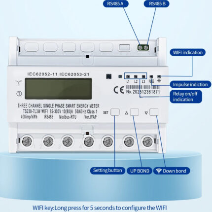
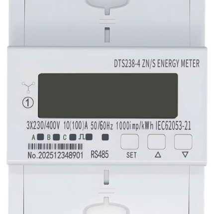
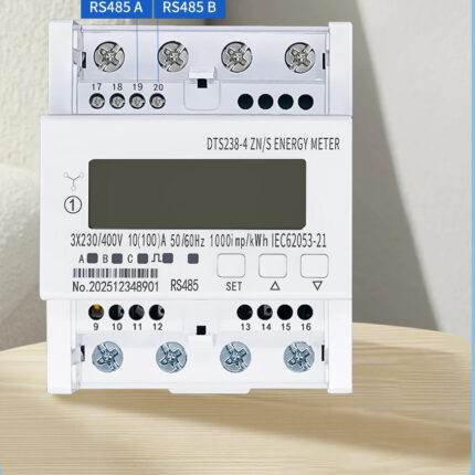
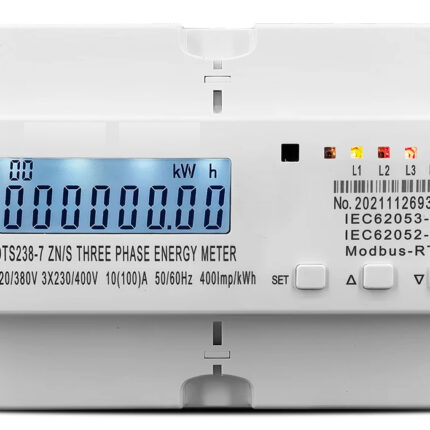
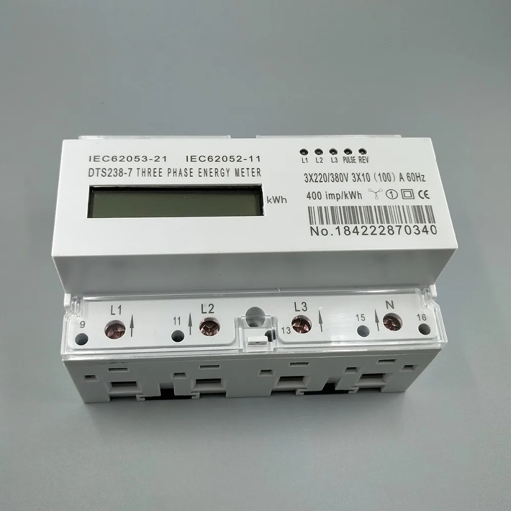
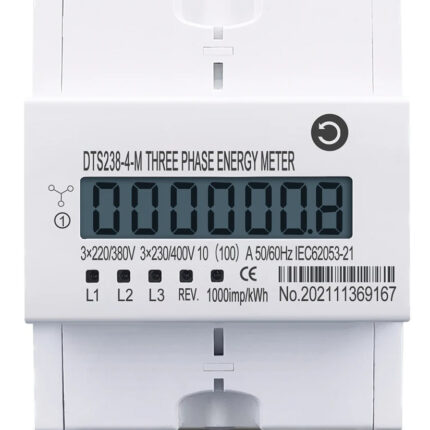
The DTS238-7 LCD energy meter measures active energy in three-phase four-wire circuits. This version is rated 3 × 220/380V, 60Hz and 10(100)A per phase, with direct connection. Its seven-module enclosure combines a local LCD, phase-status indicators and energy-pulse indication for distribution-board submetering.
Technical selection summary
| Model | DTS238-7 |
|---|---|
| System | Three-phase four-wire AC |
| Rated voltage | 3 × 220/380V AC |
| Rated / maximum current | 10(100)A per phase; direct connection |
| Frequency | 60Hz |
| Accuracy | Class 1 |
| Starting current | 0.004 Ib = 40mA |
| Energy measurement | Total active energy; reverse active energy accumulated in total |
| Display | LCD; 6+1 digit family configuration |
| Front indicators | L1, L2, L3, PULSE and REV |
| Pulse constant | 400imp/kWh on the illustrated unit |
| Pulse output | Optically isolated passive pulse output |
| Power consumption | <0.5W / 5VA per phase |
| AC withstand test | 4000V / 25mA for 60 seconds |
| Impulse withstand | 6kV, 1.2μs waveform |
| Protection / mounting | IP20; 35mm DIN rail |
| Operating temperature | −25°C to +55°C |
| Relative humidity | Below 75% in the installation environment |
| Standards marked | IEC62053-21 and IEC62052-11 |
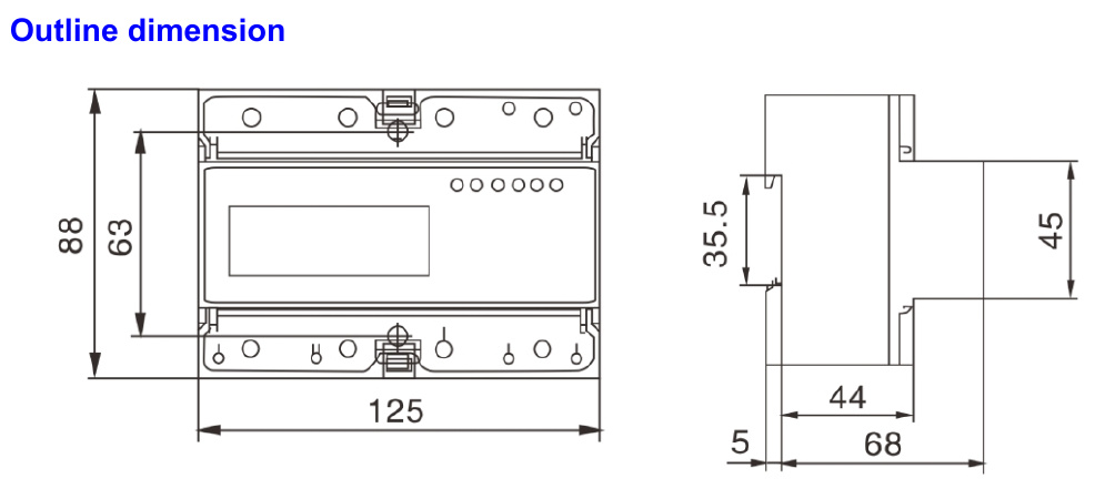
| Overall size | 125mm wide × 88mm high × 73mm overall depth |
| Drawing depth references | 68mm housing reference with 5mm projection; 44mm front reference |
Energy accumulation and phase status
The meter measures positive and negative active energy, accumulating reverse energy in the total reading. The LCD retains energy data after supply loss. L1, L2 and L3 indicators show the supply status of each phase, while PULSE and REV identify energy pulses and reverse connection or energy flow.
Three-phase four-wire direct connection
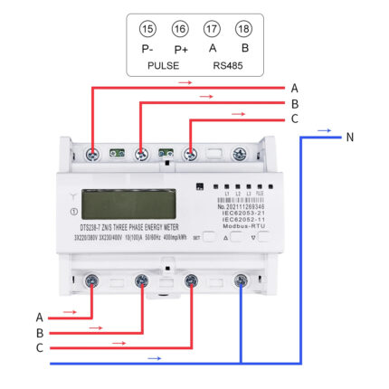
The selected 100A version connects directly to the circuit. Connect each phase and neutral through its corresponding input and output terminals, following the terminal markings and the direct-connection diagram.

| L1 / L1′ | A-phase input / output |
|---|---|
| L2 / L2′ | B-phase input / output |
| L3 / L3′ | C-phase input / output |
| N / N′ | Neutral input / output |
Terminal access and pulse indication
The terminal covers protect the wiring connections and provide sealing points. The optically isolated pulse output supports energy testing and external pulse collection. The illustrated meter is marked 400imp/kWh. Isolate the supply before wiring, and tighten the terminal screws after inserting correctly sized copper conductors.

Installation and dimensions
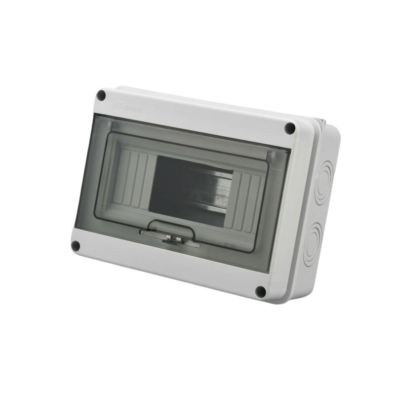
Clip the meter to a 35mm DIN rail in a suitable distribution enclosure. The body occupies seven modules and measures 125mm wide and 88mm high. The dimension drawing shows the housing and projection depth references, a 35.5mm rail section and a 45mm front section. Use an enclosure suited to the installation environment.
Typical applications
For three-phase residential, commercial and industrial energy allocation, distribution-board consumption checks and local kWh monitoring on 220/380V 60Hz systems.