




NewTrend · three-circuit smart energy monitoring
Product overview
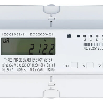
The TS238-7L3W meters and controls three single-phase circuits independently, or can be used with a three-phase circuit. This 10(80)A version combines WiFi, RS485, a backlit LCD and internal relays. Each circuit has separate energy readings, remote switching and programmable control functions.
Technical selection summary
| Model | TS238-7L3W |
|---|---|
| Circuit arrangement | Three single-phase two-wire circuits, or one three-phase circuit; common neutral |
| Rated / maximum current | 10(80)A with internal relay control |
| Working voltage | 85–300V per phase, L–N |
| Frequency | 50/60Hz |
| Normal / limit voltage range | 80–110% Un / 70–120% Un |
| Energy accuracy | Class 1 |
| Measurements | Per-circuit voltage, current, active/reactive power and power factor |
| Energy registers | Separate import and export active energy for each circuit |
| Communication | WiFi and RS485 MODBUS-RTU |
| WiFi | 802.11b/g/n; 2.4GHz network |
| RS485 | 1200–9600bps; default 9600bps; no parity |
| RS485 terminals | 21: A; 22: B |
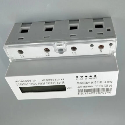
| Pulse constant | 400imp/kWh on the illustrated unit |
| APP control | Independent relay switching, timing, reset and prepayment per circuit |
| APP protection | Overvoltage, undervoltage and overcurrent settings |
| History | Hourly, daily, monthly and yearly energy records; Excel-format export by email |
| Local display | Backlit LCD with SET, up and down keys |
| Data retention | Energy retained after power loss; local metering continues without WiFi |
| Operating conditions | −25°C to +55°C; relative humidity below 75% |
| Mounting | 35mm DIN rail; bottom main-terminal wiring |
| Dimensions | 93mm high × 126mm wide × 65mm deep |
| Standard markings | IEC62052-11; IEC62053-21 |
Independent circuit measurement and switching
The LCD and APP provide imported and exported active energy for each circuit, together with real-time voltage, current, active power, reactive power and power factor. Each circuit can be switched independently through the APP, making it possible to manage three loads separately.

WiFi, RS485 and front-panel controls
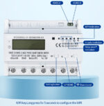
The meter supports WiFi and RS485 control at the same time. WiFi uses a 2.4GHz 802.11b/g/n network. The RS485 port uses MODBUS-RTU at 1200–9600bps, default 9600bps, with no parity. Terminal 21 is RS485 A and terminal 22 is RS485 B. The annotated front panel identifies phase relay indicators, pulse indication, WiFi status and the SET, up and down keys. Hold the WiFi key for five seconds to start network configuration.

Protection, timing and prepayment
The APP provides configurable overvoltage, undervoltage and overcurrent protection, with functions enabled or disabled as required. Overcurrent settings, timing control and prepayment are managed separately for the three circuits. When an enabled prepayment balance is exhausted, the corresponding relay disconnects automatically. Energy can be reset individually from the APP, and alarm events and switching operations are recorded for each circuit.

Energy history, export and cost tracking
The APP tracks hourly, daily, monthly and yearly active energy and can export records in Excel format by email. Imported and exported energy history can be selected from the energy window. Each circuit also provides a one-day active-power curve at 15-minute intervals, energy-cost information and carbon-emission estimates.

Local display sequence
Front-panel keys step through the per-circuit energy and electrical-parameter readings, pulse constant, meter information and communication settings. The display reference below preserves the reading codes and units for integration and local operation.

Three-circuit wiring
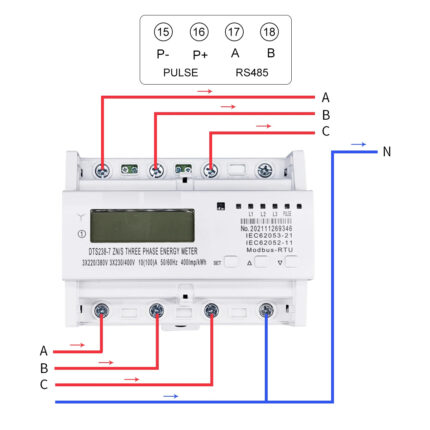
L1, L2 and L3 inputs may be supplied from the same single-phase line or from a three-phase supply, using the common-neutral arrangement shown. Main current wiring enters and leaves at the bottom of the meter. Follow the terminal diagram and isolate the supply before installation or servicing.

MODBUS register map
The register map lists the three circuits’ energy, voltage, current, power and relay-status data, together with access permissions, scaling and communication settings. It supports remote reading and the documented control functions for each circuit.

Dimensions and data retention
The enclosure is 93mm high, 126mm wide and 65mm deep, with 51mm depth and 45mm front-section references in the drawing. Mount it on a 35mm DIN rail in a suitable distribution enclosure. Energy data is retained after power loss. Metering continues when the WiFi connection is lost, and APP readings update after reconnection.

Typical applications
For independent monitoring and control of three single-phase loads, three-phase distribution monitoring, bidirectional energy tracking, scheduled loads and connected submetering systems.