



NewTrend · DC circuit breaker
Product overview
The TOB1Z-125 is a DC circuit-breaker family for overload and short-circuit protection. This page covers the two-pole 600 V DC version and explicitly includes the popular TOB1Z-125 2P 600V 125A specification. The photographed 125 A unit is marked C125, DC600V and 10kA. The series name and the 125 A hot specification are covered on one page.

Technical selection summary
| Series | TOB1Z-125 |
|---|---|
| Hot specification | TOB1Z-125 2P 600V 125A |
| Offered poles/voltage | 2P /600 V DC |
| Current options | 63,80,100 and125 A;63 A confirmed by original catalogue,80/100/125 A by the web parameter table and photographs |
| Characteristic | C; catalogue release reference C:12In ±20% |
| Breaking capacity | 10 kA; catalogue Ics=Icu=10,000 A |
| Insulation voltage Ui | 1000 V, original catalogue |
| Impulse withstand Uimp | 6 kV (1.2/50 μs), original catalogue |
| Mechanical life | 20,000 operations |
| Electrical life | At least8,000 operations, web parameter table |
| Protection degree | IP20 |
| Standards | IEC/EN60947-2 and GB14048.2 on unit; web family table also lists EN60898/IEC60898 |
| Ambient reference | Catalogue−5 to+40 °C with daily mean≤35 °C; web table−10 to+40 °C |
| Storage temperature | −25 to+70 °C |
| Thermal-setting reference temperature | 30 °C |
| Terminals | Cable, U-type busbar or pin-type busbar, catalogue reference |
| Cable cross-section | 25 mm²; catalogue also prints18–3 alongside the cable entry |
| Terminal torque | 3.0 N·m, catalogue |
| Mounting | 35 mm DIN rail, fast clip |
| Connection | Top and bottom, follow polarity/terminal diagram |
| Dimensions | 2P width54 mm; catalogue87 mm height and74 mm side reference; web drawing gives76 mm side reference |
Current-rating reference
The original web image confirms the 80,100 and 125 A variants and 10 kA capacity. The complete original catalogue additionally lists 63 A. The electrical characteristics and dimensions must follow the supplied two-pole 600 V unit.

Installation
The original installation reference shows DIN-rail mounting and the power-terminal arrangement. Isolate the circuit before installation or maintenance.

DC circuit wiring
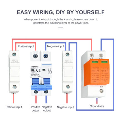
Observe the polarity and terminal numbering marked on the breaker. The original system illustration includes separate fuse holders and a DC surge protector; those devices are not included with this breaker.

Product identification
The original annotated view identifies model, current rating,600 V DC marking, breaking capacity, terminals, operating handles and polarity-specific wiring diagram.

Rear view and web dimensions
The original reference retains the rear clips and detailed two-pole dimensions. Its 76 mm side reference differs from the 74 mm catalogue drawing, so check actual enclosure fit.

Complete original electrical and installation data
The original technical page below retains the full general description, current/pole/voltage matrix, breaking capacity, impulse withstand, release characteristics, installation data . This listing offers 2P 600V with the C characteristic; other pole/voltage combinations remain catalogue references.
The downloadable PDF retains both complete original pages, including headers, layout and footers.

Tripping curves, wiring and mounting drawings
The complete second page retains the B/C curves,1P–4P DC wiring diagrams and mounting dimensions. The selected configuration on this page is 2P 600V C characteristic.

Typical applications
DC distribution and photovoltaic equipment requiring overload and short-circuit protection. The source also identifies communications, transport and industrial DC equipment as applications.