

NewTrend · photovoltaic branch connections
Product overview
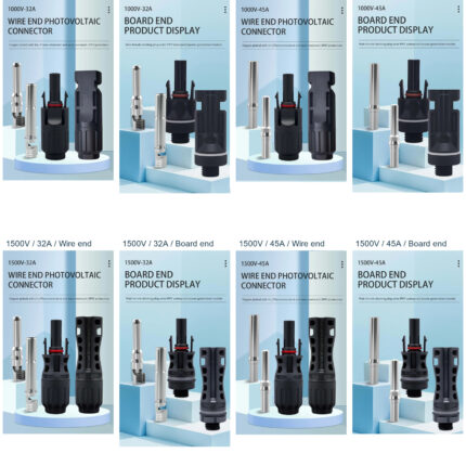
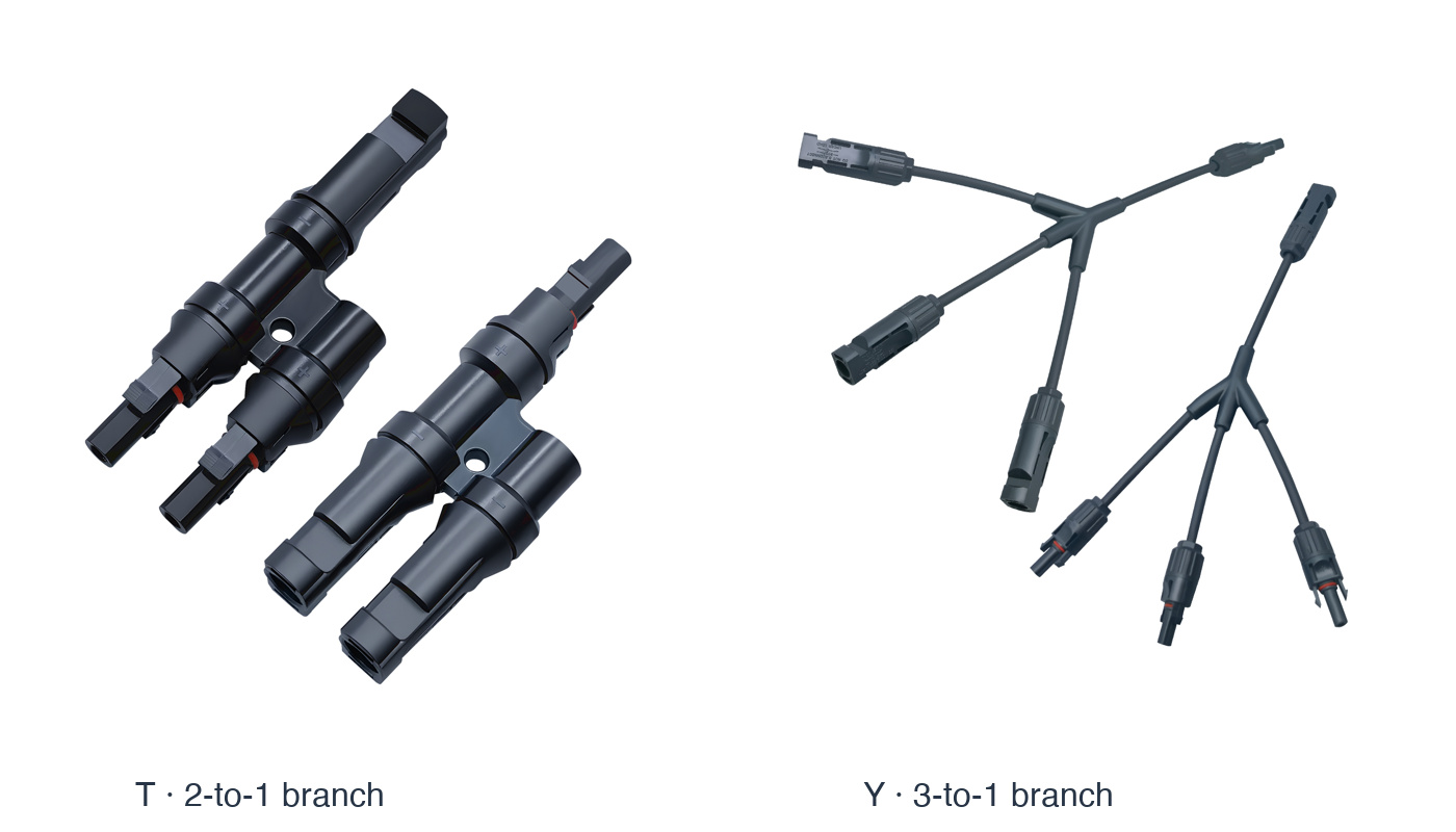
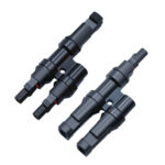
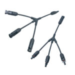
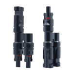
These PV branch connectors provide parallel connection points for solar-panel wiring. Choose the compact rigid T branch for a 2-to-1 arrangement or the flexible Y cable branch for a 3-to-1 arrangement. Each selected set contains a positive and a negative assembly. Both types are rated for systems up to 1000V DC, with current limits matched to the selected branch type.
Technical selection summary
| T branch configuration | Rigid 2-to-1 / 1-to-2 branch; positive and negative pair |
|---|---|
| Y branch configuration | Flexible 3-to-1 / 1-to-3 cable branch; positive and negative pair |
| Working voltage | Up to 1000V DC |
| T branch current rating | 32A |
| Y branch working-current limit | ≤30A |
| Ingress protection | IP67 when correctly assembled and fully mated |
| Y branch housing / contacts | PPO insulating housing; plated copper contacts |
| Y branch cable sizes | 2.5 / 4.0 / 6.0mm² mating cable-connector reference |
| Y branch insulation resistance | >500MΩ |
| Y branch dielectric-test reference | 6000V DC |
| Y branch temperature range | −40°C to +125°C |
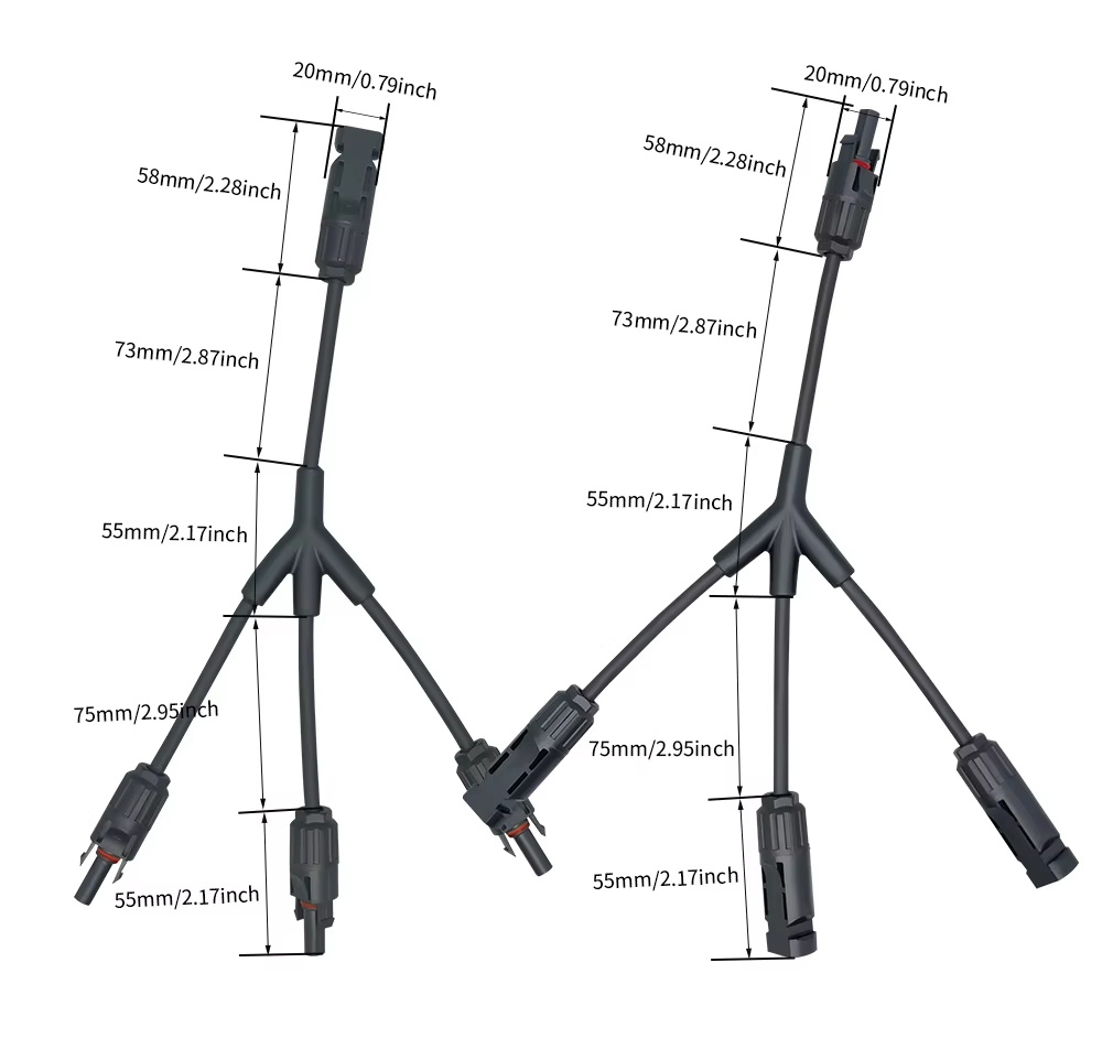
| Y branch connector dimensions | 20mm wide; 58mm connector section at the common end |
| Y branch lead / junction references | 73mm common-end lead; 55mm junction; 75mm branch lead and 55mm branch-end connector sections |
| Connection features | Locking connector housings, polarity marks and sealing rings |
| Supplied set | One positive and one negative branch assembly for the selected type |
Rigid T branch
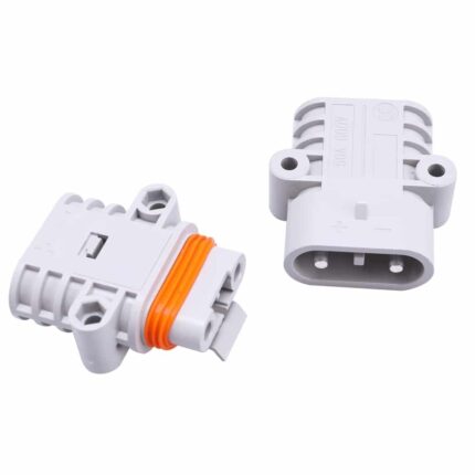
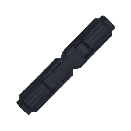
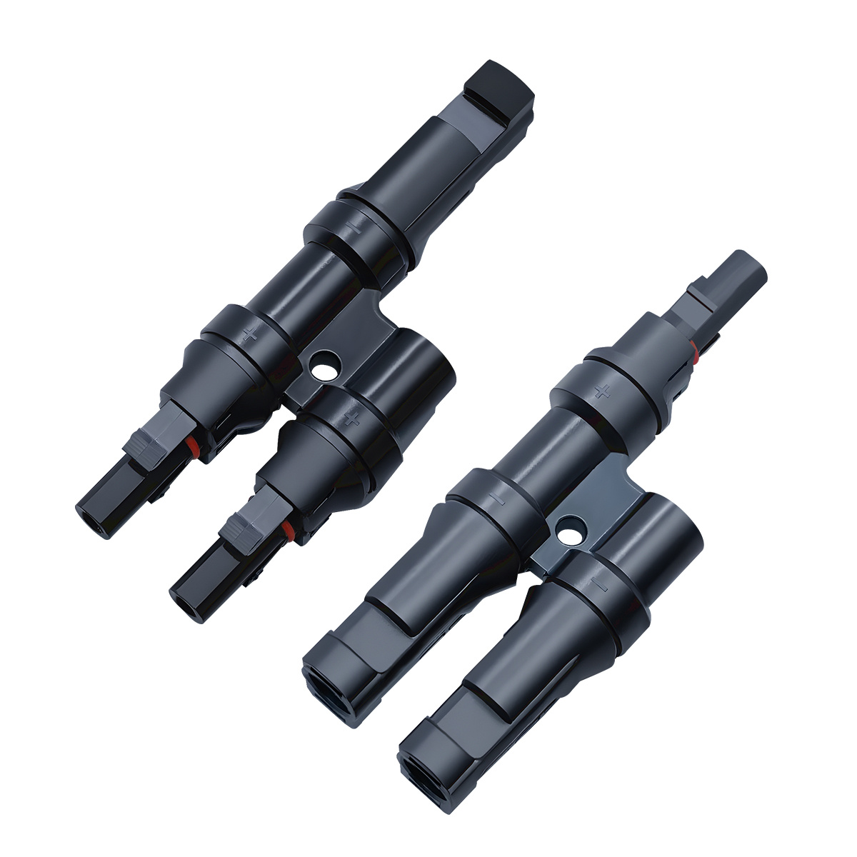
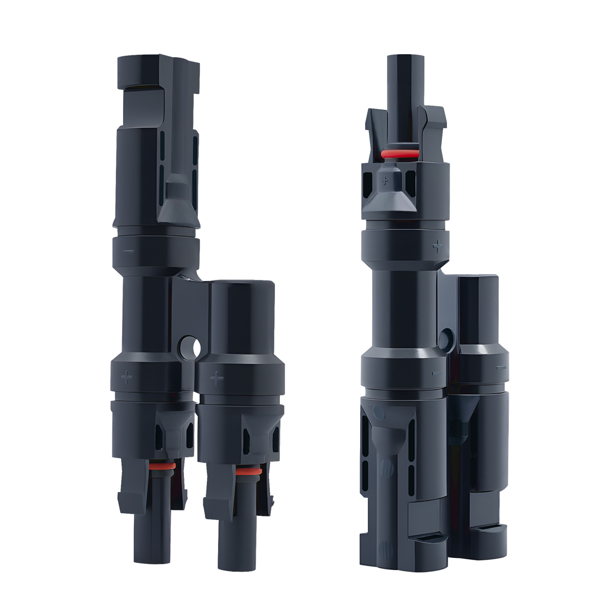
The T assembly provides two branch connectors and one common connector in a compact rigid body. The positive and negative pieces have different mating arrangements and polarity marks. This version has a 32A current rating. Its locking housings and sealing rings support a secure, properly mated connection.
Flexible Y cable branch
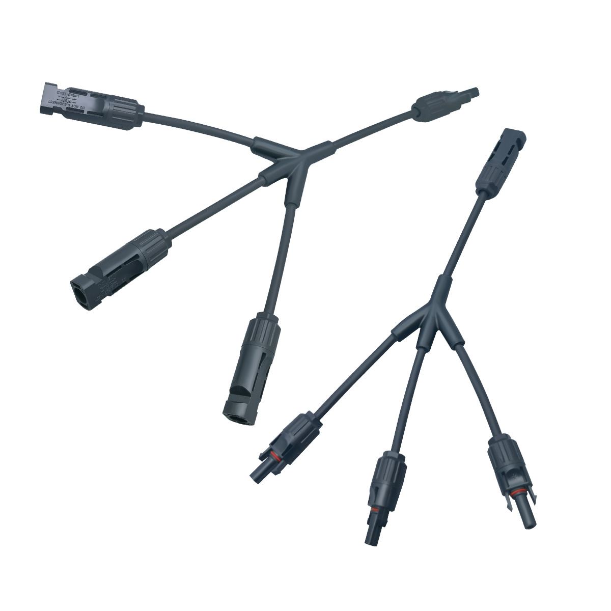
The Y assembly provides three branches and one common end, with flexible leads around the moulded junction for easier cable positioning. Its technical working-current limit is 30A. Keep the combined current at the common end within this limit and match the assembly to the circuit conductors, protective devices and connector counterparts.
Y branch dimensions
The drawing identifies a 20mm connector width and 58mm common-end connector section. It also shows a 73mm common-end lead, a 55mm junction, 75mm branch leads and 55mm branch-end connector sections. Use these individual dimensions for routing and clearance rather than treating the flexible branches as a fixed overall width.
Cable-connector assembly and installation
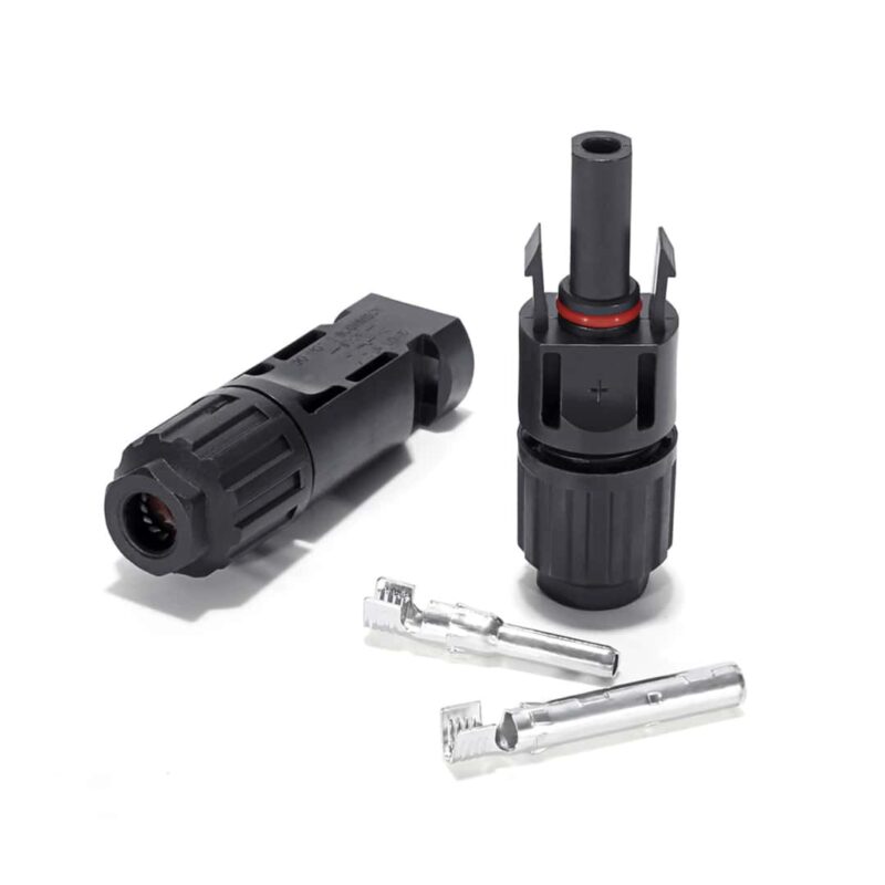
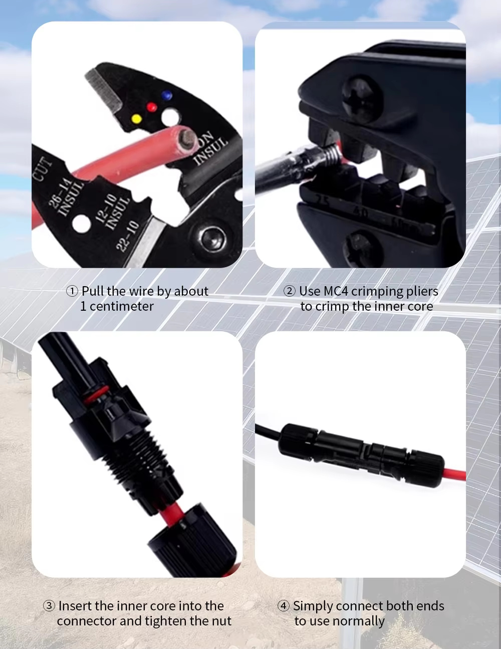
The illustrated installation sequence applies to mating cable connectors: prepare the conductor, crimp the matching contact with a suitable tool, insert the contact into its housing and tighten the cable gland. Match contact size to the 2.5, 4.0 or 6.0mm² cable reference. Check polarity, contact seating, sealing rings and locking engagement before energizing. Keep the moulded branch junction intact and do not disconnect PV connectors under load.
Outdoor use and applications
For compatible PV-panel wiring, combiner-box connections and inverter-side DC cable arrangements. The IP67 connection requires correct assembly and fully mated seals. Use matching connector counterparts and maintain cable support, bending clearance and protection appropriate to the installation.