


NewTrend · photovoltaic connectors
Product overview
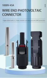
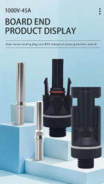
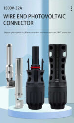
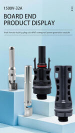
These PV solar connectors join photovoltaic DC cables or provide a panel-mounted connection at an enclosure. Choose a 1000V DC or 1500V DC version, 32A or 45A rating, and wire-end or board-end construction. Each version uses matched male and female housing and contact components.
Technical selection summary
| Model | MC4 |
|---|---|
| Product type | PV solar connector; male and female contact / housing components |
| Rated current options | 32A or 45A |
| Rated voltage options | 1000V DC or 1500V DC |
| Mounting options | Wire end or board end (panel mounting) |
| Conductor cross-section | 2.5 / 4 / 6mm² |
| Housing material | PPO |
| Contacts | Plated copper contacts |
| Insulation resistance | >500MΩ |
| Test voltage | 6000V DC |
| Protection | IP67 when correctly assembled and mated |
| Temperature range | −40°C to +125°C |
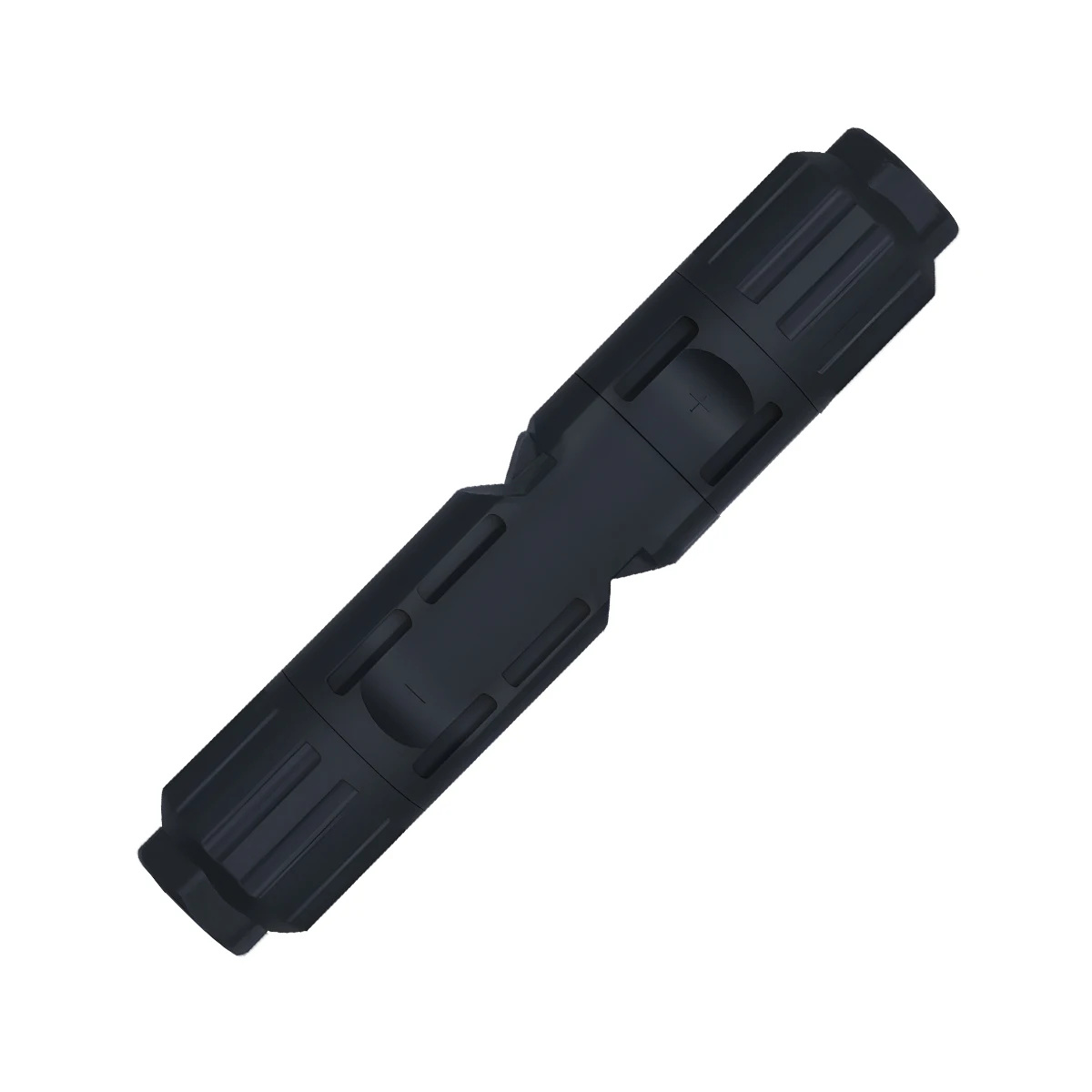
| Locking | Snap-lock male / female coupling |
| Installation | Crimped conductor termination; cable sealing nut on wire-end versions |
Wire-end and board-end versions
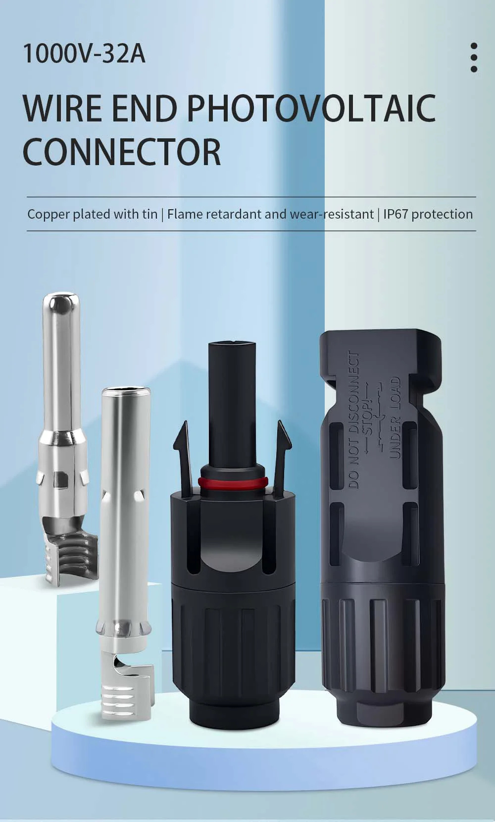
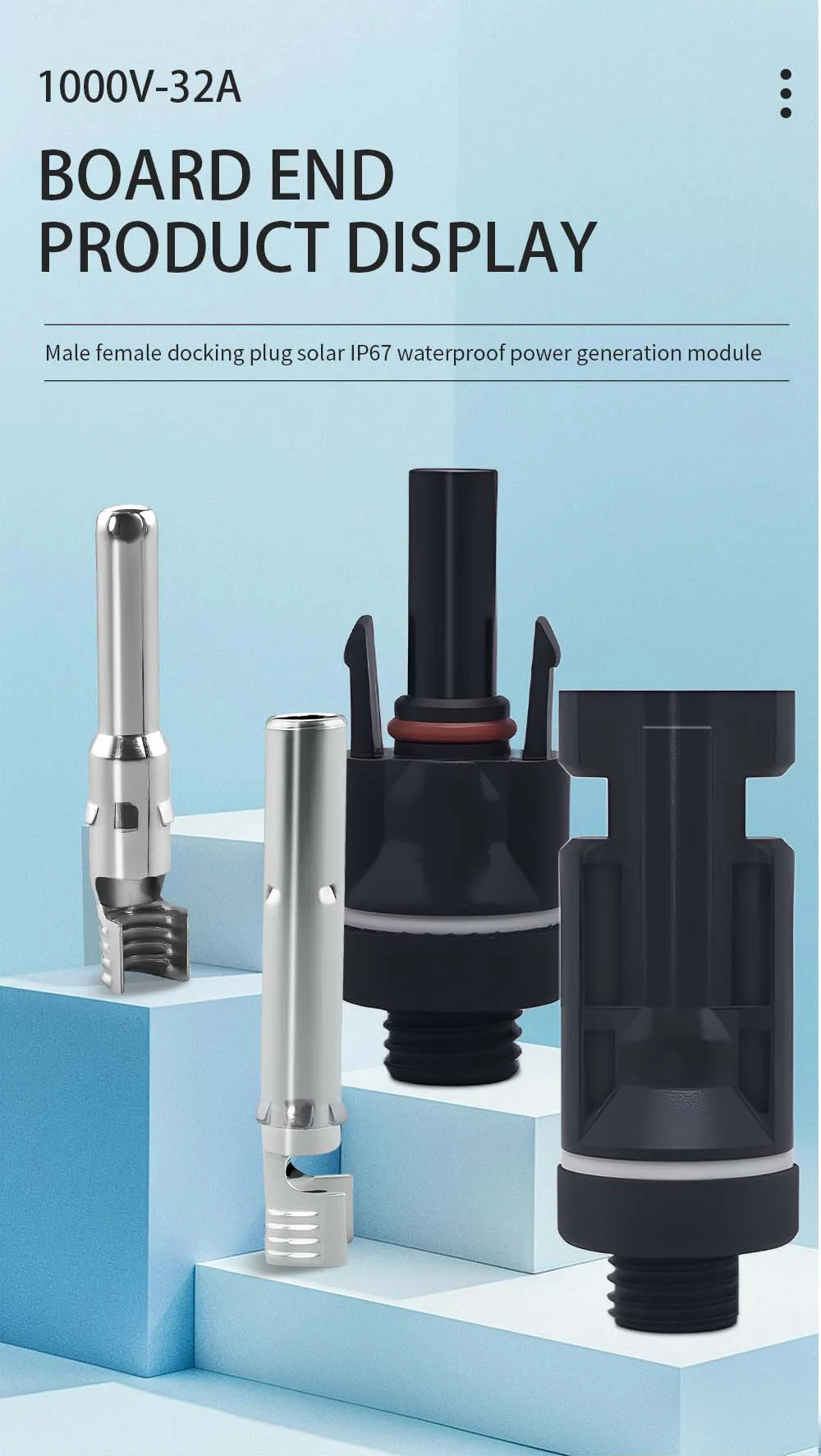
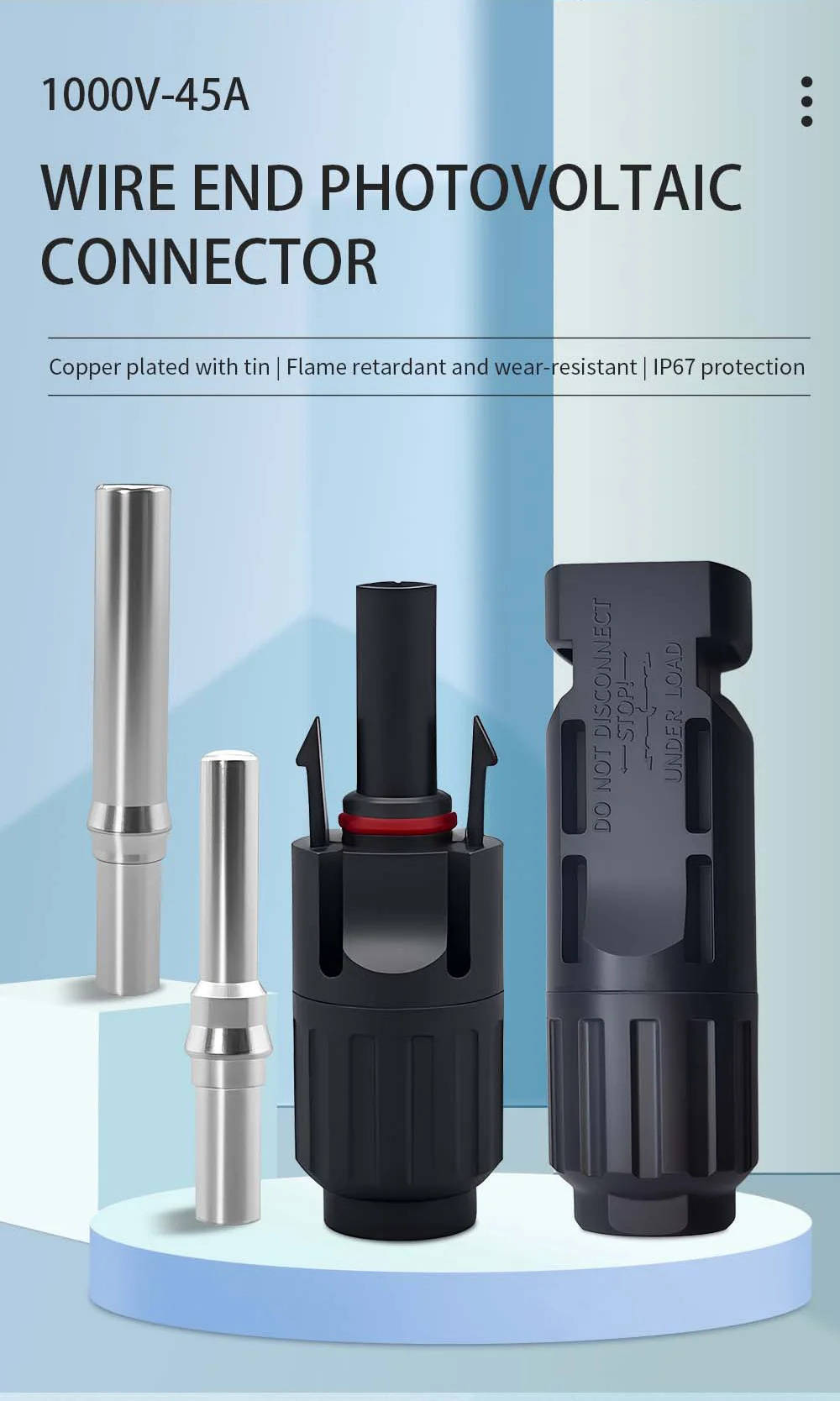
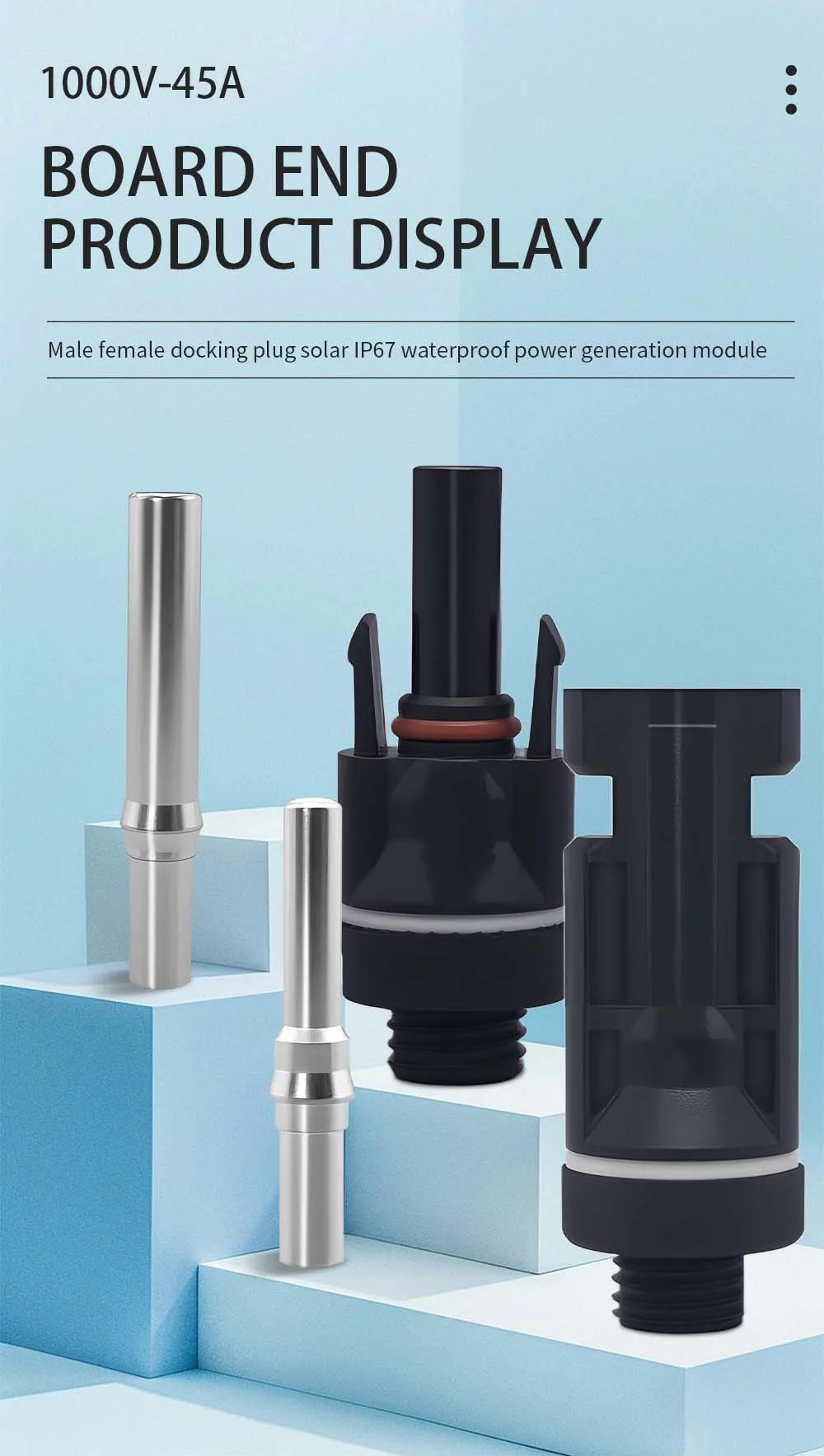
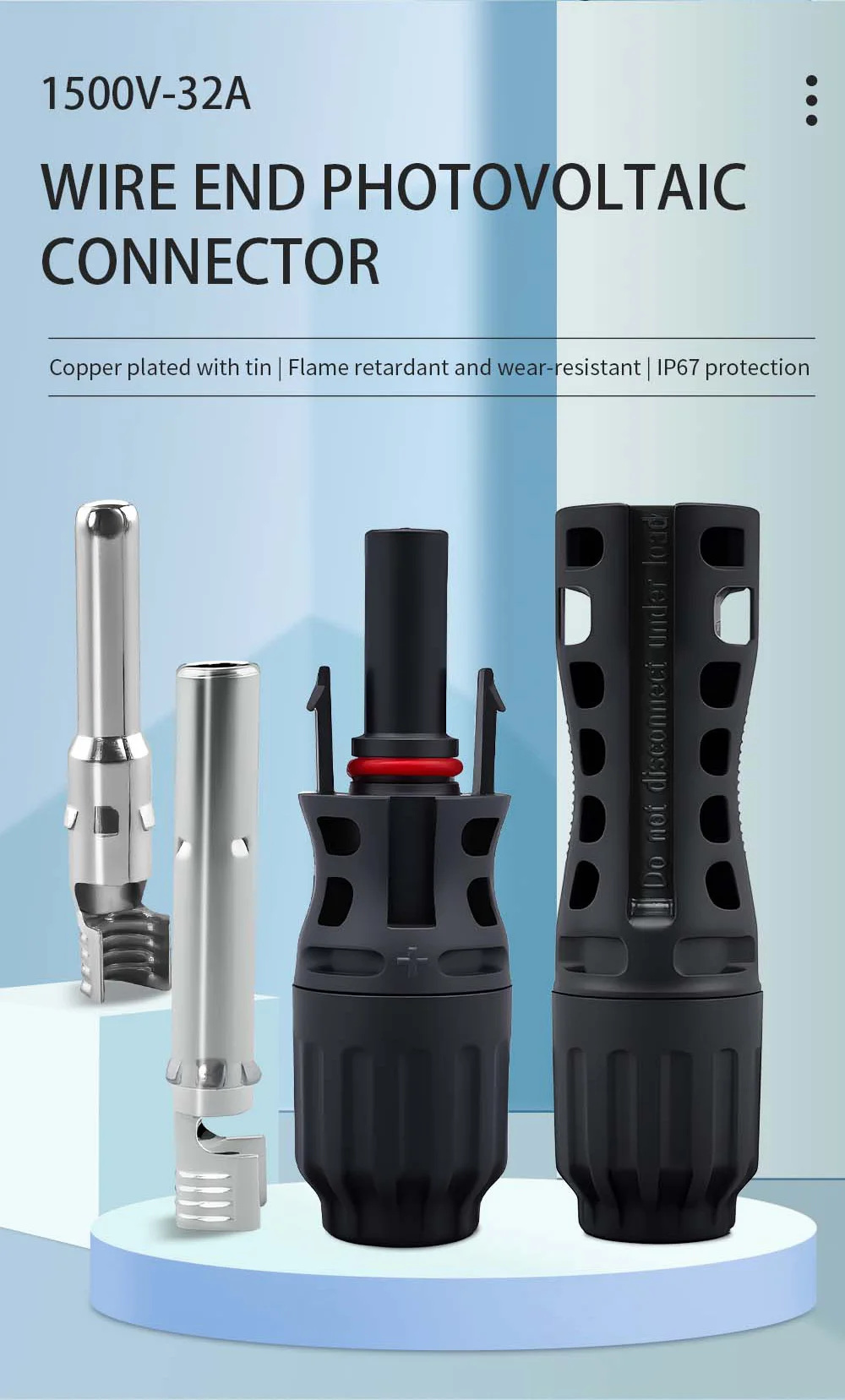
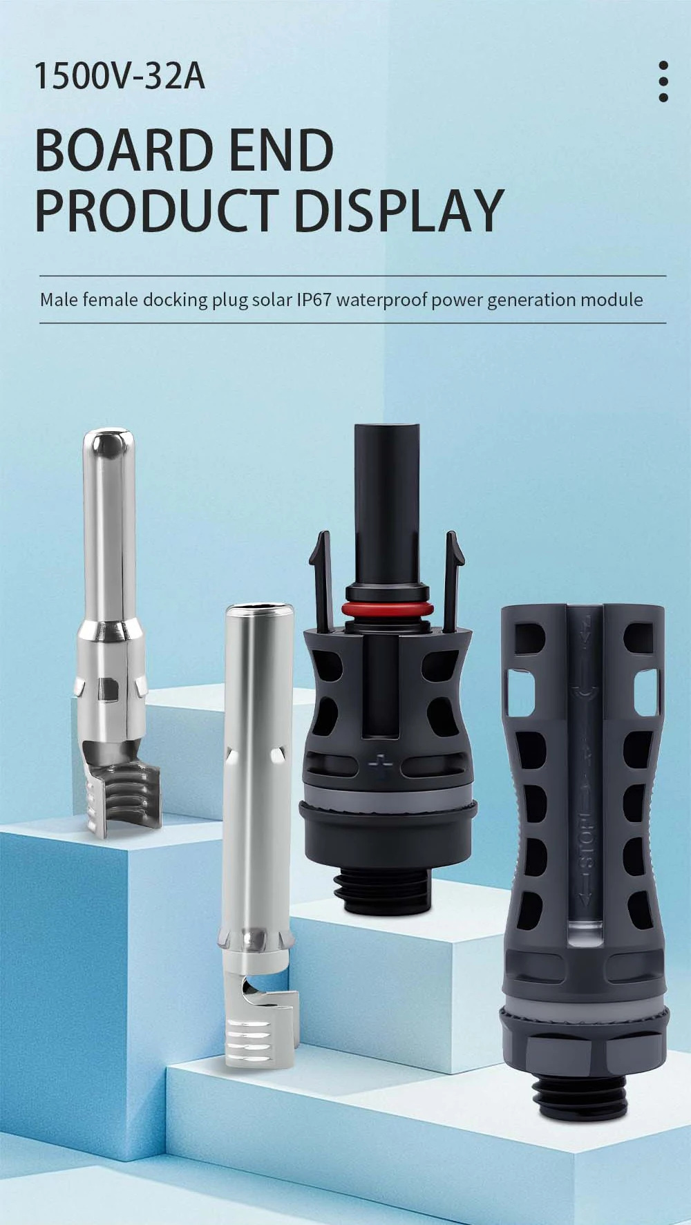
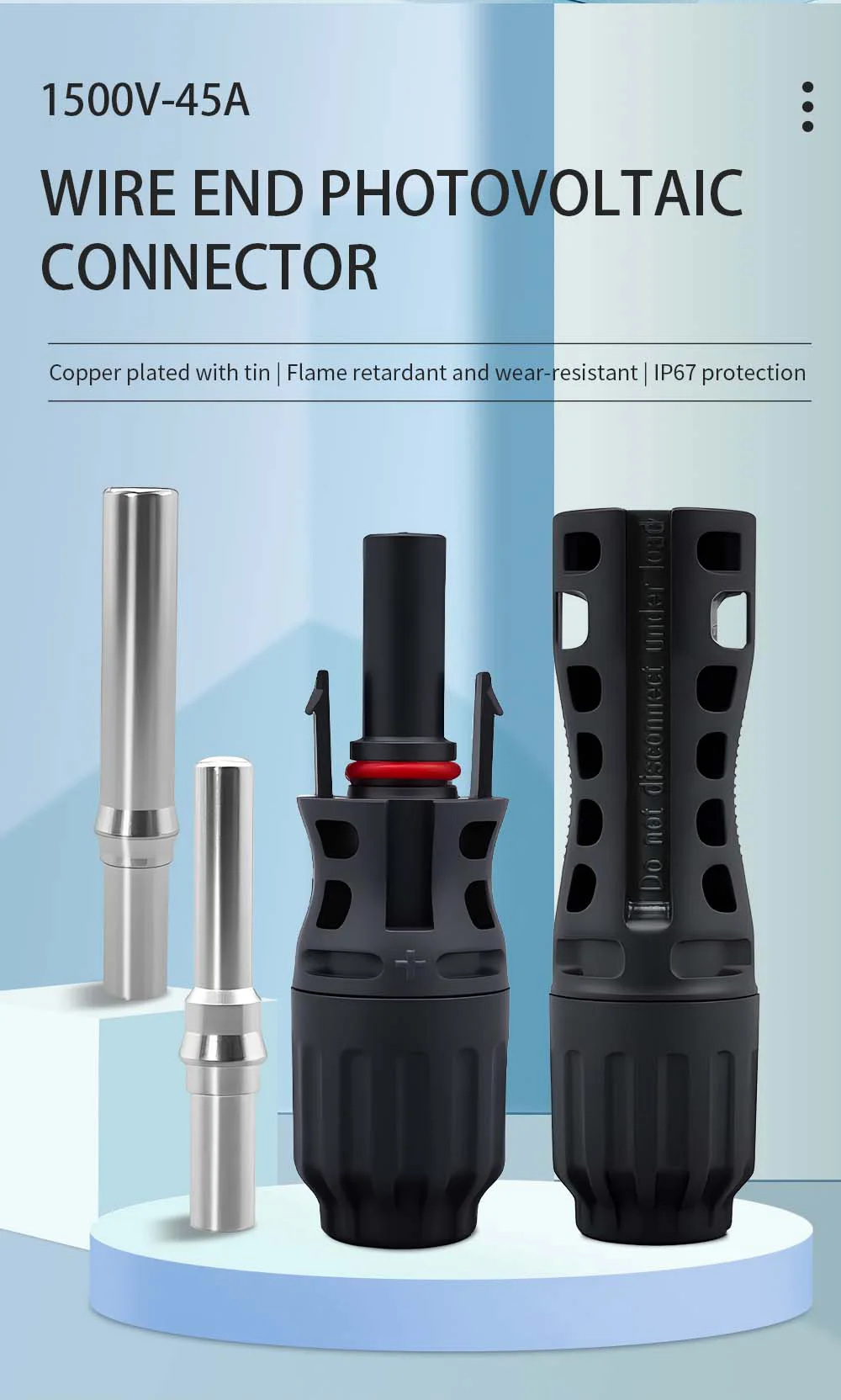
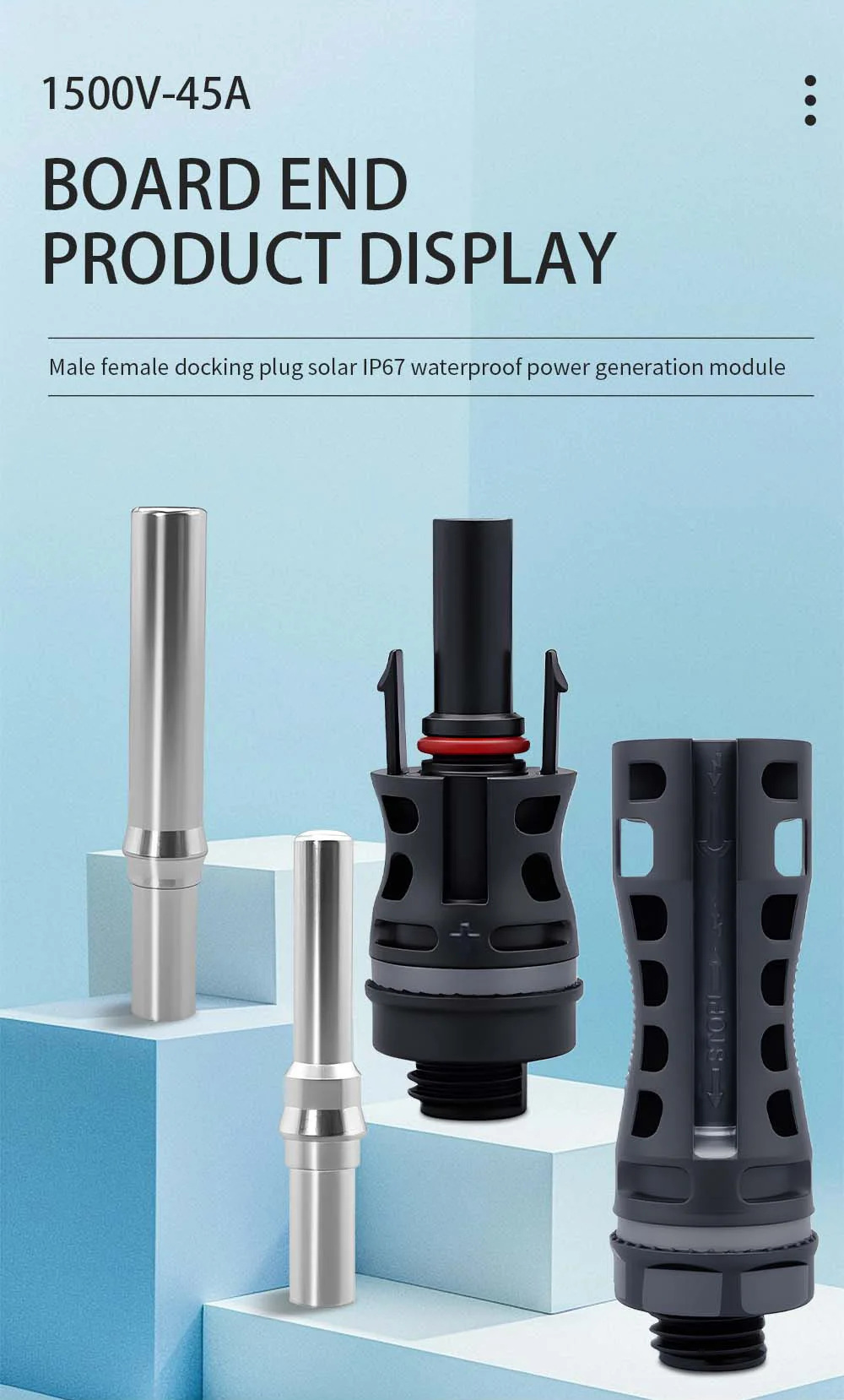
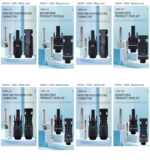
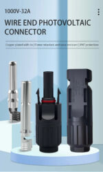
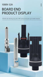
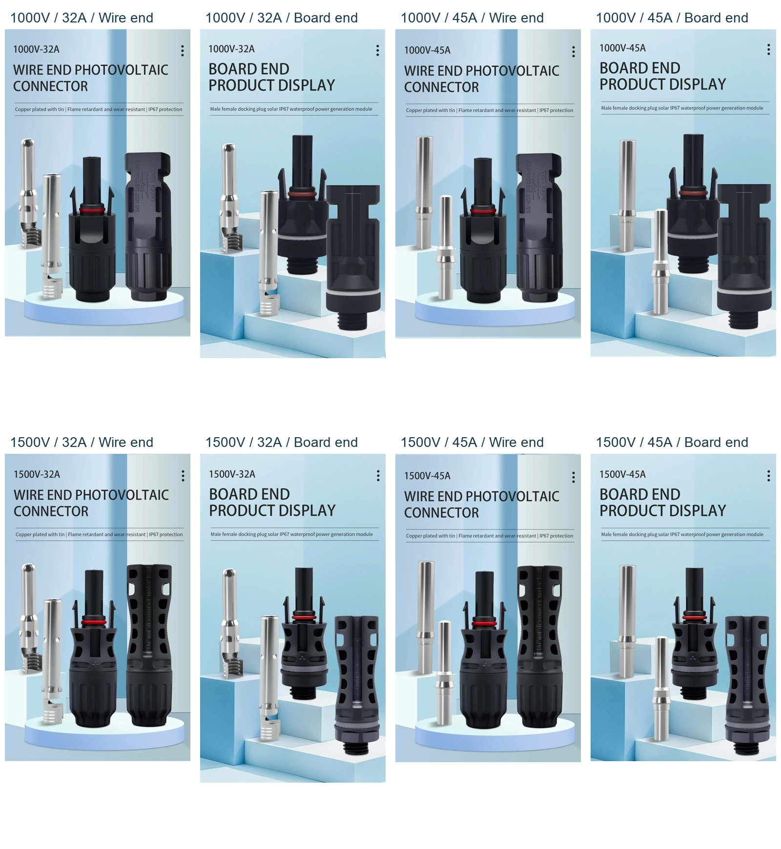
Wire-end connectors terminate flexible PV cabling with a cable gland and sealing nut. Board-end versions have a threaded panel-mounting section for installation on a suitable enclosure. The overview below shows all eight voltage, current and mounting combinations; select the corresponding rating before assembly.
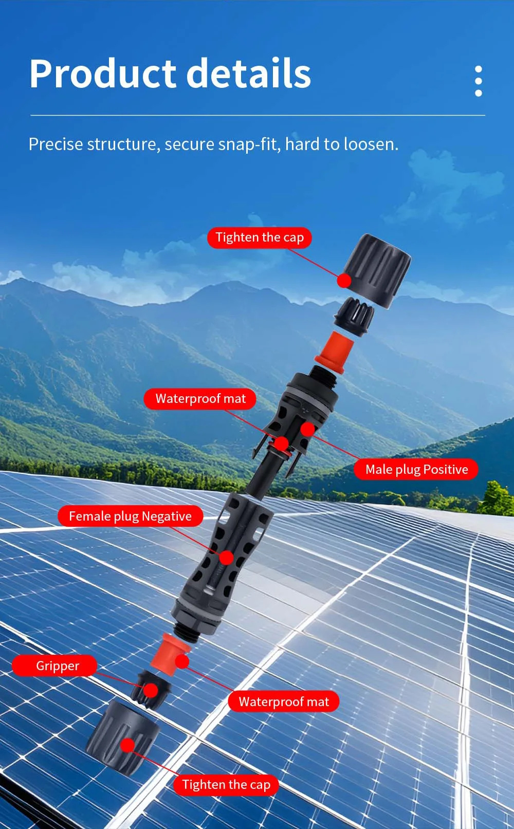
Housing, seal and locking system
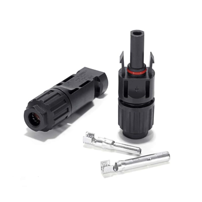
The PPO housing surrounds the copper contact system. A sealing ring and tightened cable nut provide the specified protection when the connector is correctly assembled and mated. The coupling locks into place to resist accidental separation. Maintain the cable seal and use a conductor size suited to the selected contact.
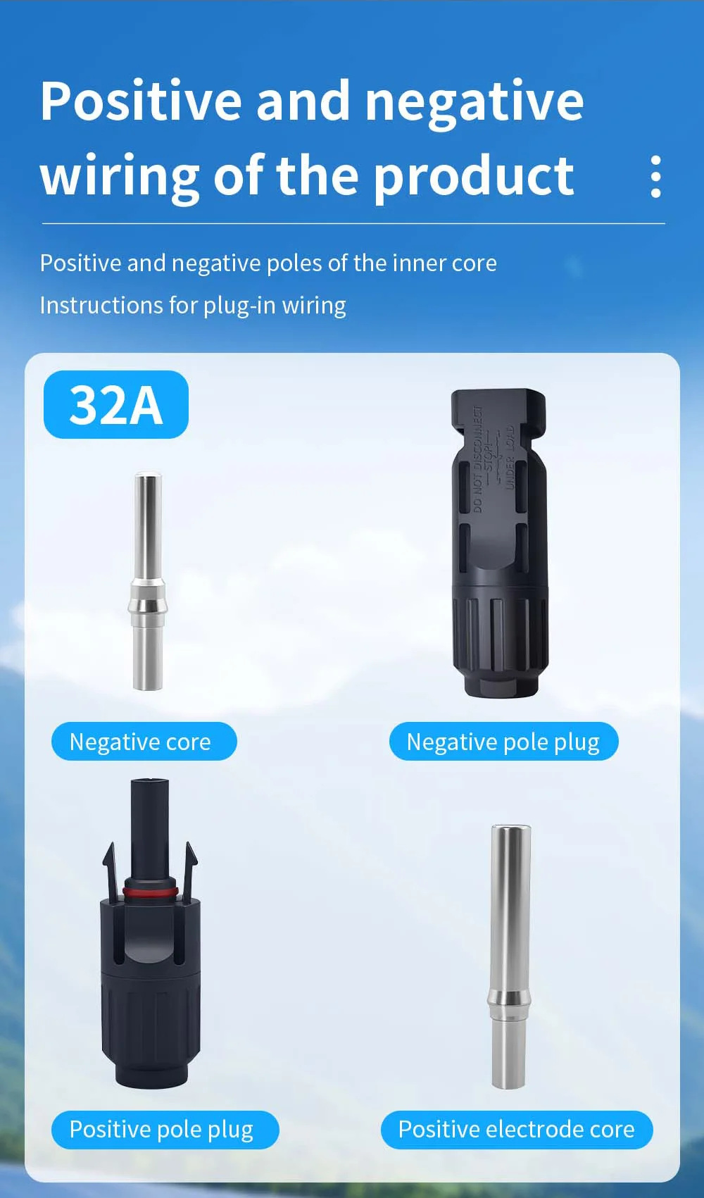
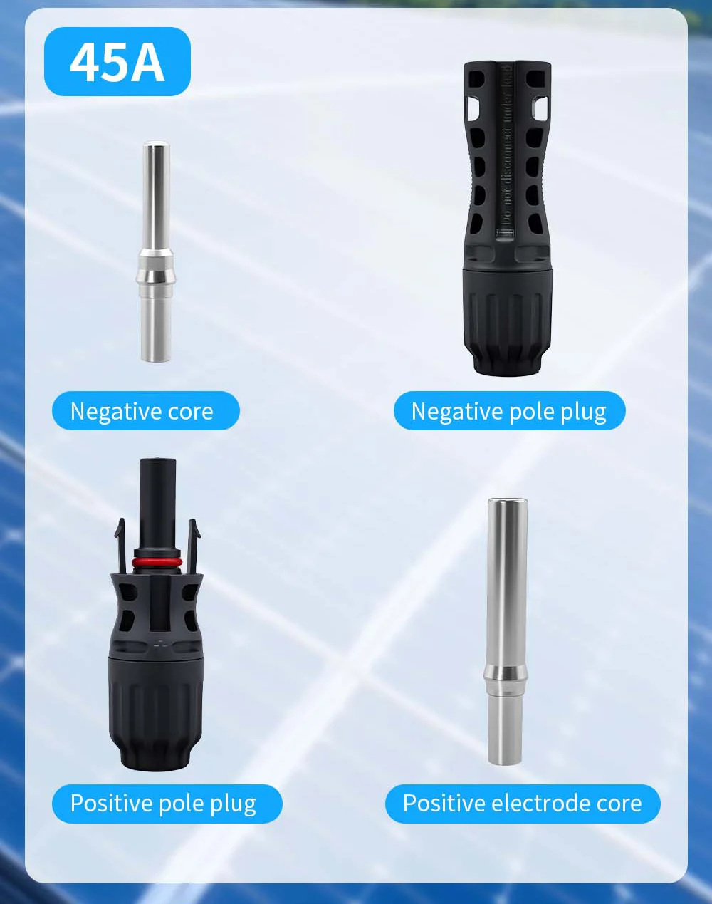
32A and 45A contact components
The illustrations identify the positive and negative housing and contact components for the two current ratings. Use the contact and housing parts belonging to the same voltage, current and mounting version. Verify polarity throughout the circuit before energizing.
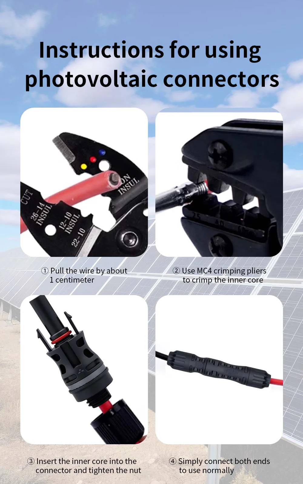
Crimping and assembly
Isolate the DC circuit before installation. Strip the cable without damaging the conductor, crimp the correct contact with a suitable tool, insert it fully into its housing and tighten the sealing nut. Couple the matching connectors until the latch engages and check the connection mechanically. Do not disconnect under load. Match connector components within the specified system rather than assuming interchangeability from appearance alone.
Dimensions and connector outlines
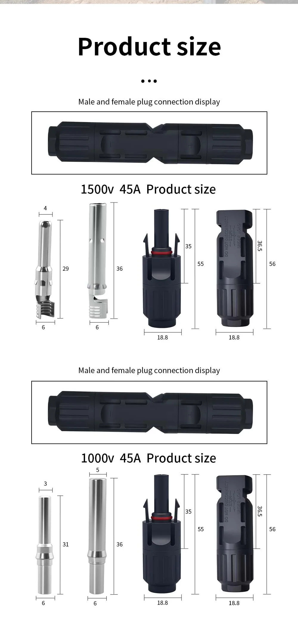
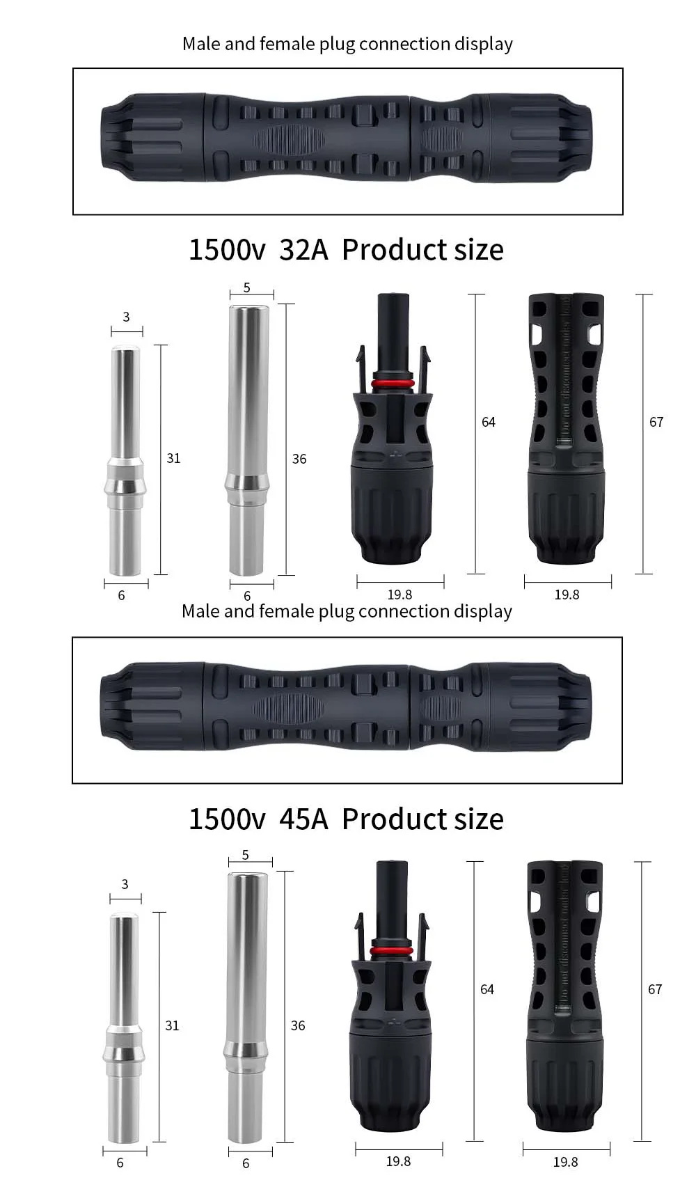
The following drawings show the contact and housing outlines of the illustrated wire-end versions, with dimensions in millimetres. Board-end construction uses a different mounting arrangement; allow appropriate panel and cable clearance.
Typical applications
For DC cable connections in photovoltaic arrays, combiner boxes and inverter-side wiring, within the voltage and current rating of the selected version. Install and service with the circuit isolated, using appropriate DC protection and cable routing.