




NewTrend · manual transfer switch (MTS)
Product overview
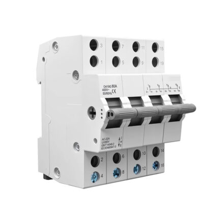
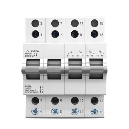
The O419G is a four-pole, 125 A manual transfer switch that combines four functions in one device: On, Off, Transfer and Isolation. It moves one load between two supplies — normally the city mains on one side and an inverter, a generator or a standby feed on the other — and it does so with a visible break at the handle rather than with contactors and a control circuit.
Four poles means three phases plus neutral are switched together. A single-phase load tapped from the same changeover point therefore cannot be left tied to a neutral that still belongs to the source you have just disconnected. All four poles ride on one shaft under one handle, and a mechanical interlock keeps the two incoming supplies apart: closing one path physically blocks the other, so a welded contactor upstream, a control-circuit fault or two operators working at once cannot put both supplies on the load.
The 125 A rating and the 144 mm width put this version at the high-current end of the series. It is built for feeders and sub-mains where the changeover carries the full load current continuously, not just during the transfer.
Four functions, three handle positions
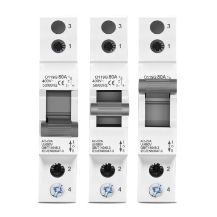
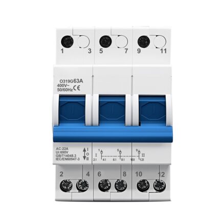
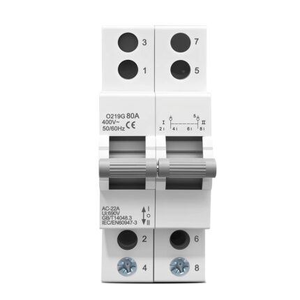
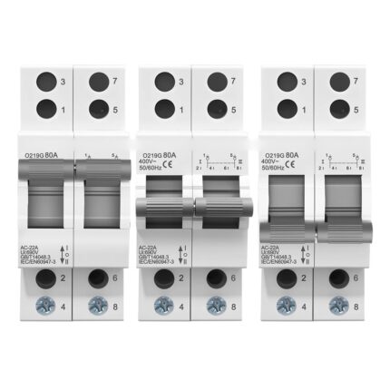
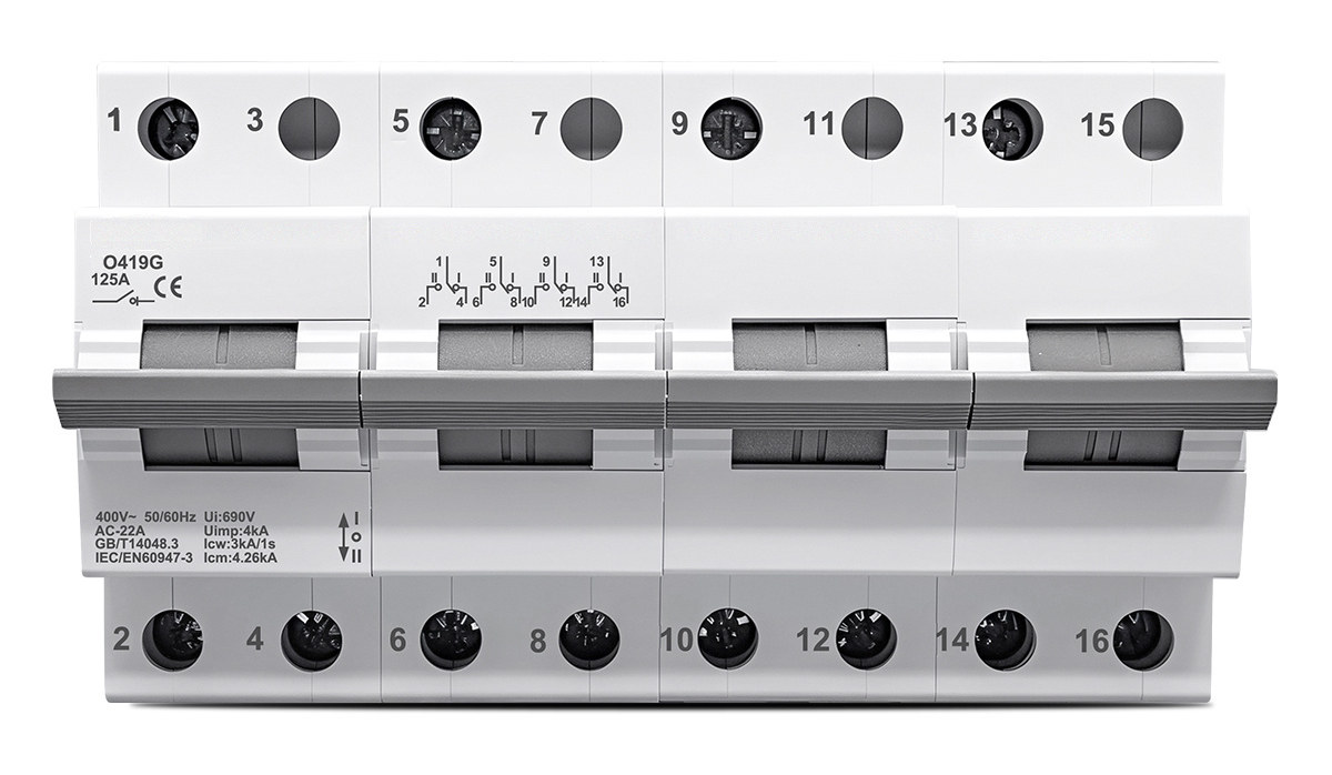
The front of the device carries a printed changeover diagram for each pole, with the terminal numbers of the two sources and the load. The handle has three stable positions:
- I — 1–2, 5–6, 9–10 and 13–14 are connected. The load is fed from the normal supply.
- II — 1–4, 5–8, 9–12 and 13–16 are connected. The load is fed from the standby supply.
- Centre — both groups are open. Every pole is isolated from either source, and the break is visible at the handle.
On, Off, Transfer and Isolation are therefore not four separate devices but four states of the same mechanism. Because the interlock is mechanical rather than electrical, the isolation position cannot be defeated by a wiring error or a failed coil, and the handle can be locked in the centre position for work on the load side.
Technical data
The values below are the ones printed on the device and on the manufacturer’s reference drawings for this model. Rated voltage is marked 400 V~ AC; the changeover is a four-pole device intended for three-phase systems with a switched neutral, so check the marking against the installation before commissioning.
| Model | O419G |
|---|---|
| Product type | Manual transfer switch (MTS), dual-power changeover, disconnectable |
| Functions | On, Off, Transfer, Isolation |
| Poles | 4P (three phases + neutral) |
| Rated current | 125 A |
| Rated voltage | 400 V AC (device marking 400 V~) |
| Frequency | 50/60 Hz |
| Utilization category | AC-22A |
| Contact form | 1-0-2, three positions (I / OFF / II) |
| Insulation voltage (Ui) | 690 V |
| Rated impulse withstand (Uimp) | 4 kV |
| Short-time withstand current (Icw) | 3 kA / 1 s |
| Rated short-circuit making capacity (Icm) | 4.26 kA |
| Standards | IEC/EN 60947-3, GB/T 14048.3 |
| Mounting | 35 mm DIN rail (35 × 7.5 mm), spring clip with screwdriver release |
| Terminals | 1, 3, 5, 7, 9, 11, 13, 15 at the top; 2, 4, 6, 8, 10, 12, 14, 16 at the bottom |
| Width | 144 mm (four 36 mm modules) |
| Height | 85 mm |
| Housing | Flame-retardant PA66 polyamide |
Handle, housing and mounting
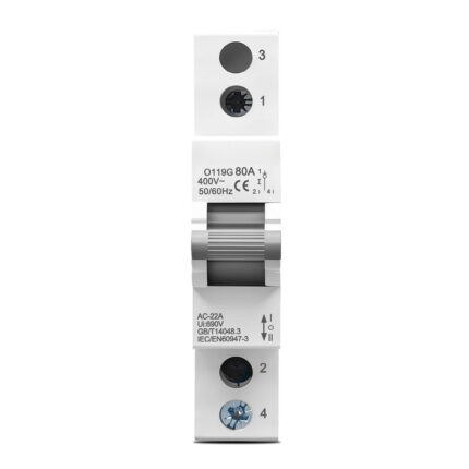
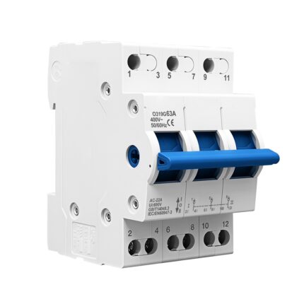
The operating handle is wider and deeper than a miniature-breaker lever and is ribbed along its length, which gives a firmer grip for the changeover stroke and a clear visual indication of the selected position. The four poles are driven from the same shaft, so the handle position always describes the state of every pole at once — there is no way to operate one pole and leave the others behind, which is the arrangement that matters when a neutral is being switched alongside the phases.
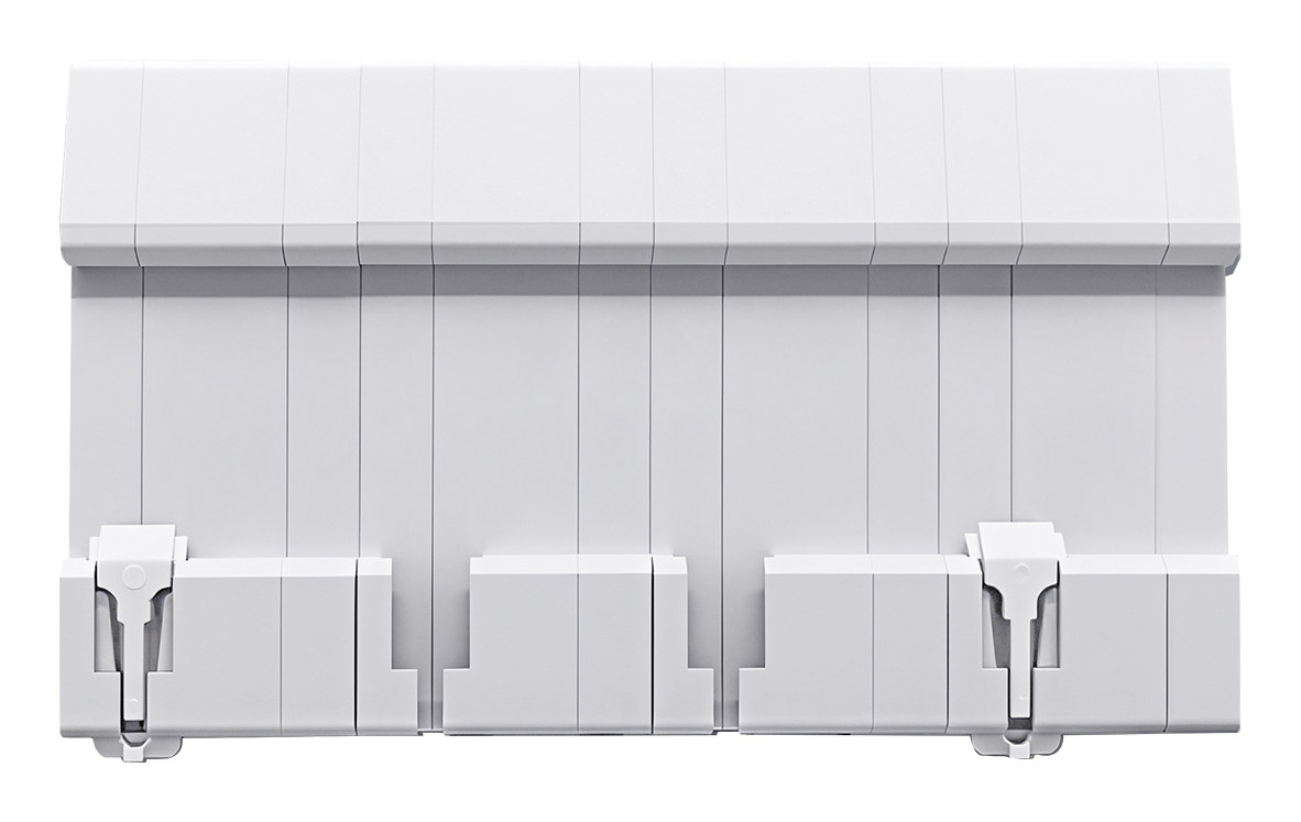
The body is moulded in flame-retardant PA66 polyamide. The grade is self-extinguishing and keeps its mechanical strength and its shape at the temperatures reached at a cable lug carrying 125 A continuously, which is where heat concentrates in a transfer switch of this size. The terminal blocks are sized for the conductors that go with a 125 A device rather than for the 80 A version of the same body.
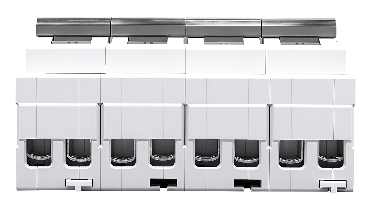
Installation uses the standard 35 mm rail: the device clips on with the spring-loaded foot at the bottom and is released with a screwdriver in the slot, so it can be fitted or removed without disturbing the modules on either side. At 144 mm the four-pole device occupies four 36 mm modules, and the side profile stays flat enough to butt directly against adjacent devices.
Wiring
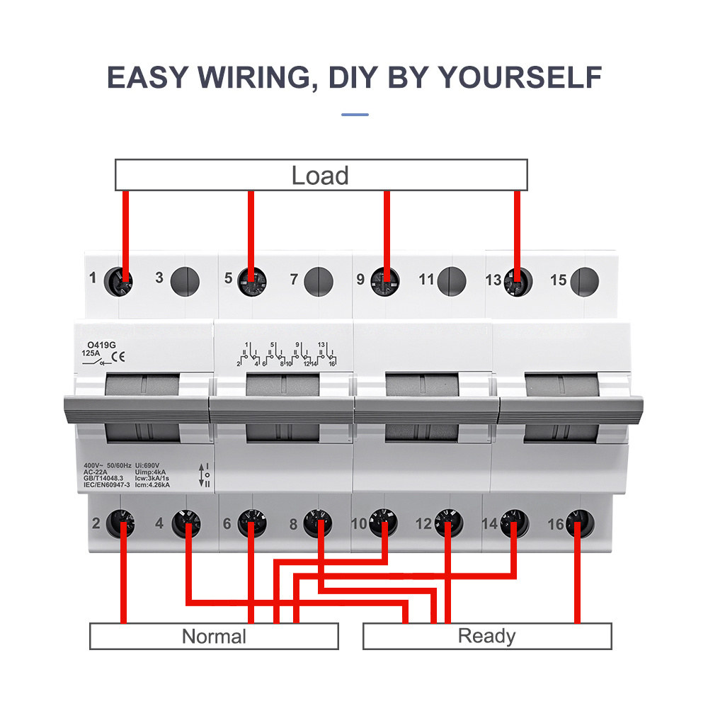
Terminal numbering follows the device: 1, 3, 5, 7, 9, 11, 13, 15 along the top and 2, 4, 6, 8, 10, 12, 14, 16 along the bottom. Each pole has one terminal on the line side and a pair on the load side, one for each source, which is what allows a single four-pole device to select between two supplies.
For dual-power changeover the manufacturer specifies feeding the normal supply and the standby supply from the lower terminals and taking the load from the upper terminals, which is the arrangement drawn on the front face and in the wiring diagram below. With the handle at I the load is fed from the normal supply; at II it is fed from the standby supply; at OFF both paths are open and the load is isolated.
Where the device is used purely as an isolator on a single line, the position of the incoming and outgoing wires can be arranged to suit the panel. The restriction applies only to dual-power use: there, the lower-in and upper-out arrangement must be kept, so that the two sources and the load are never swapped between the two changeover paths.
Typical applications
- Manual changeover between the city mains and a three-phase inverter or generator, with the neutral switched alongside the phases.
- Isolation and source selection on distribution and control panels feeding three-phase loads with a neutral.
- Feeders and sub-mains where a 125 A changeover carries the full load current continuously.
- Load transfer where a visible, lockable disconnect position is required.
- Pumping, ventilation, compressors and three-phase machines that must not be fed from two sources at once.
- Peak-valley tariff switching and PV self-consumption systems with a grid back-up path.