



NewTrend · manual transfer switch (MTS)
Product overview
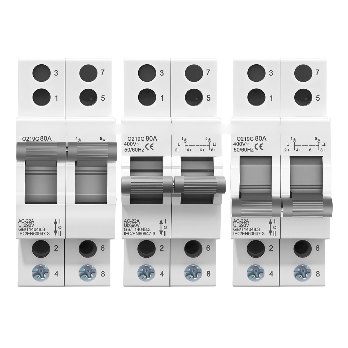
The O219G is a two-pole, 80 A manual transfer switch for moving one single-phase load between two supplies. Both poles of the load are switched together, so live and neutral are opened and closed by the same handle and the load cannot be left with one conductor still connected. The handle has three stable positions — I, centre OFF and II — and the mechanical interlock keeps the two sources apart, so the incoming supplies cannot be paralleled by mistake.
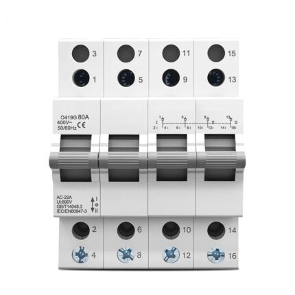
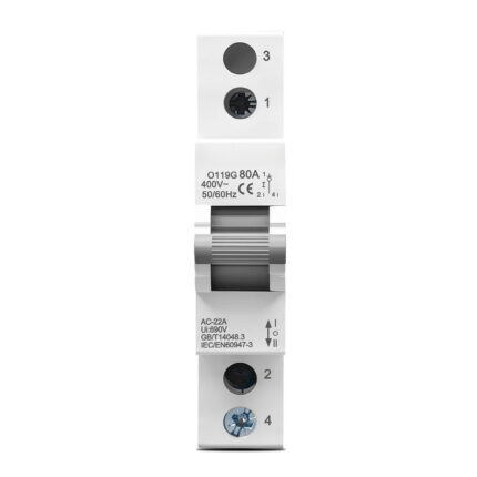
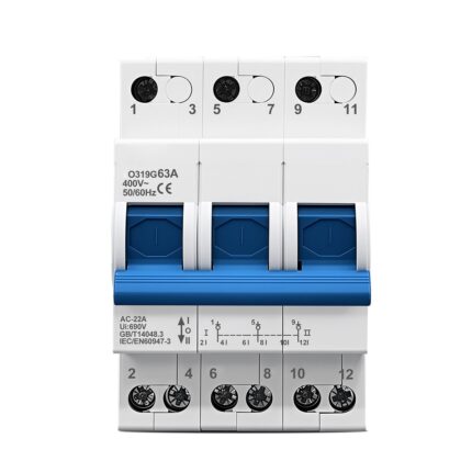
It is the 2P 80 A member of the O119G family and takes two 18 mm module spaces on the rail. The terminal numbering, handle travel and mounting depth are shared with the 1P, 3P and 4P versions, so a panel laid out for this device can be extended later without changing the rail layout. The device is marked AC-22A, Ui 690 V, 50/60 Hz, IEC/EN 60947-3 and clips onto 35 mm DIN rail.
Dual power isolation with three switching positions
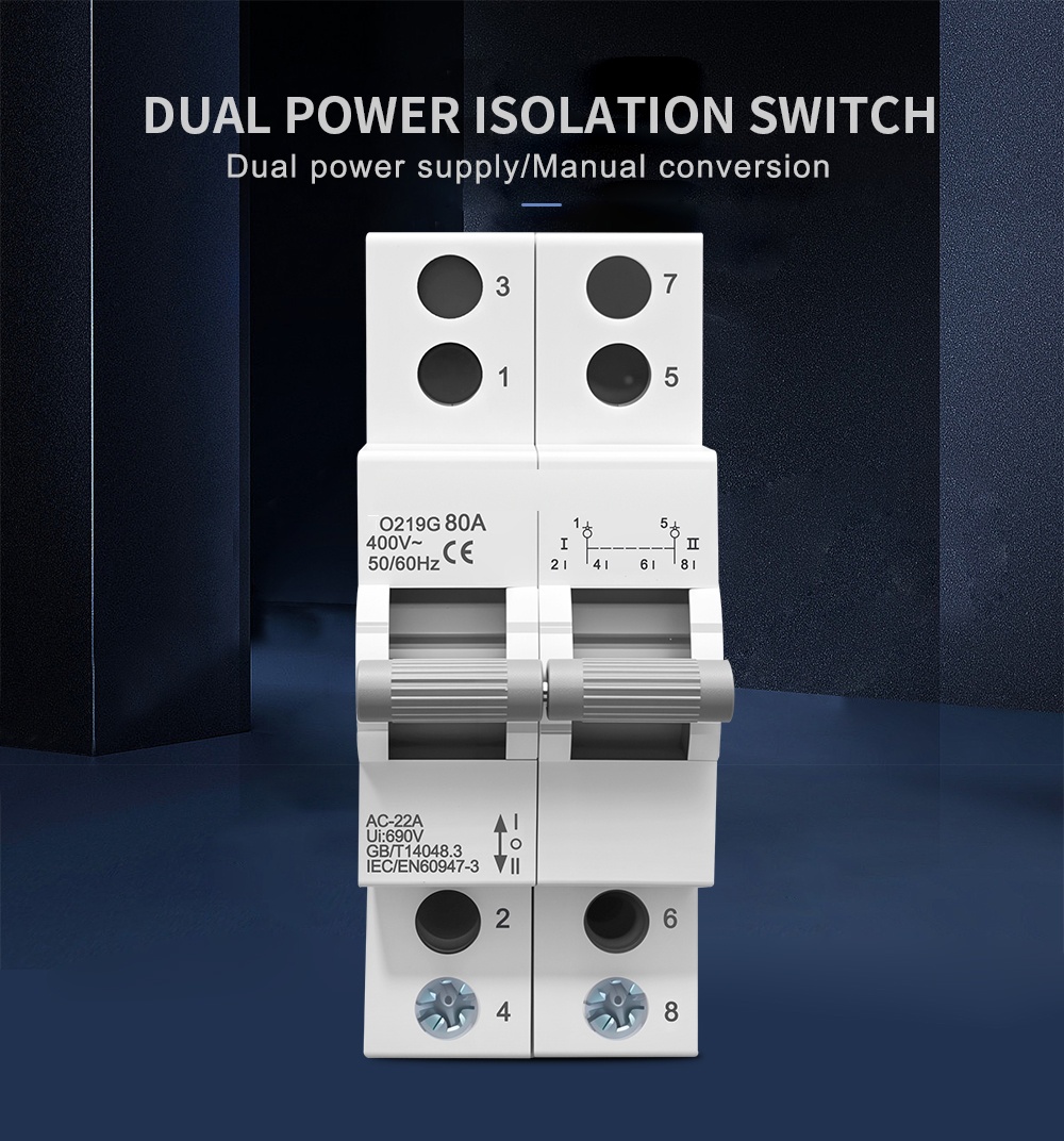
The switch is built for the two-supply case: mains on one side, generator or standby supply on the other, and one load that must never see both at once. The handle sits in the middle of the front face and travels through three detents — I, OFF and II. In the centre position the moving contacts are separated from both sets of fixed contacts, so the load is isolated from either source and the gap is visible at the handle.
The interlock is mechanical rather than electrical. Because the single handle can only be in one position, closing one path physically prevents the other from closing, and the changeover cannot be defeated by a control-circuit fault or by two operators working at once.
Technical data
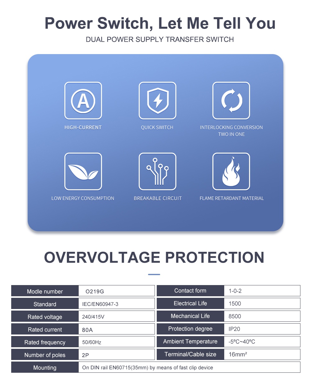
The figures below are the values published by the manufacturer for this model. Rated voltage is quoted as 240/415 V in the source data sheet — the phase-to-neutral value for a two-pole device — while the marking on the supplied unit reads 400 V~; check the marking against the installation before commissioning.
| Model | O219G |
|---|---|
| Product type | Manual transfer switch (MTS), dual-power changeover, disconnectable |
| Poles | 2P |
| Rated current | 80 A |
| Rated voltage | 240/415 V AC (source data sheet); device marking 400 V~ |
| Frequency | 50/60 Hz |
| Utilization category | AC-22A |
| Contact form | 1-0-2 |
| Insulation voltage (Ui) | 690 V |
| Electrical life | 1500 operations |
| Mechanical life | 8500 operations |
| Protection degree | IP20 |
| Ambient temperature | -5 °C to +40 °C |
| Terminal capacity | 16 mm² |
| Standards | IEC/EN 60947-3, GB/T14048.3 |
| Mounting | 35 mm DIN rail (EN 60715), fast clip device |
| Terminals | 1, 3, 5, 7 at the top; 2, 4, 6, 8 at the bottom |
| Width | 36 mm (two 18 mm modules) |
Handle, housing and mounting
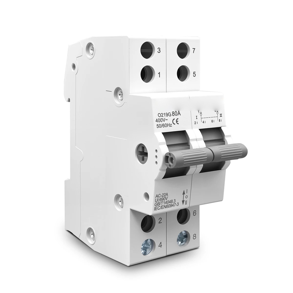
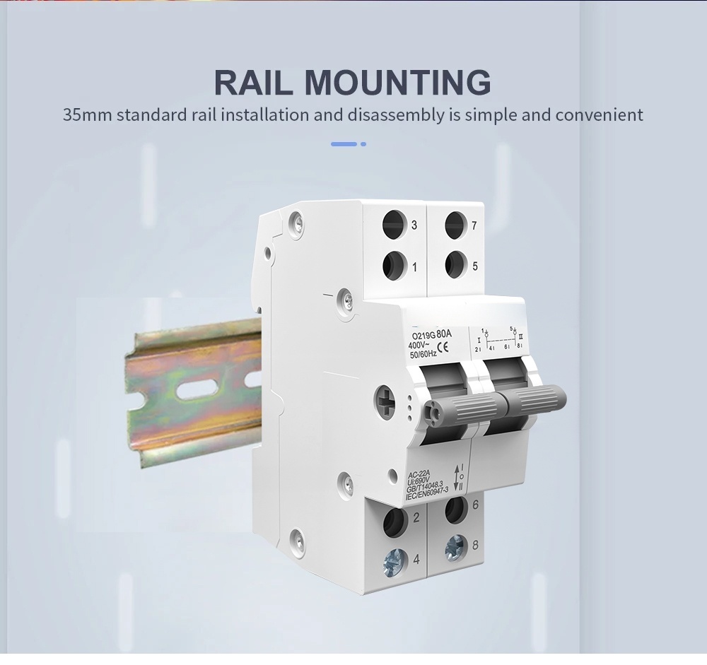
The operating handle is widened and given a deeper grip than a standard miniature breaker lever, which makes the changeover stroke easier to complete by hand and gives a clearer visual indication of the selected position. Both poles move on the same shaft, so there is no way to operate one pole and leave the other behind.

The body is moulded from a thermosetting plastic rather than a thermoplastic. Thermosets cure into a cross-linked structure, so they do not soften, flow or drip when the terminals run hot; the housing keeps its mechanical strength and its shape at temperatures that would deform an ordinary thermoplastic enclosure. That matters at the point where the cable lug meets the terminal, which is where heat concentrates in a transfer switch used continuously at 80 A.

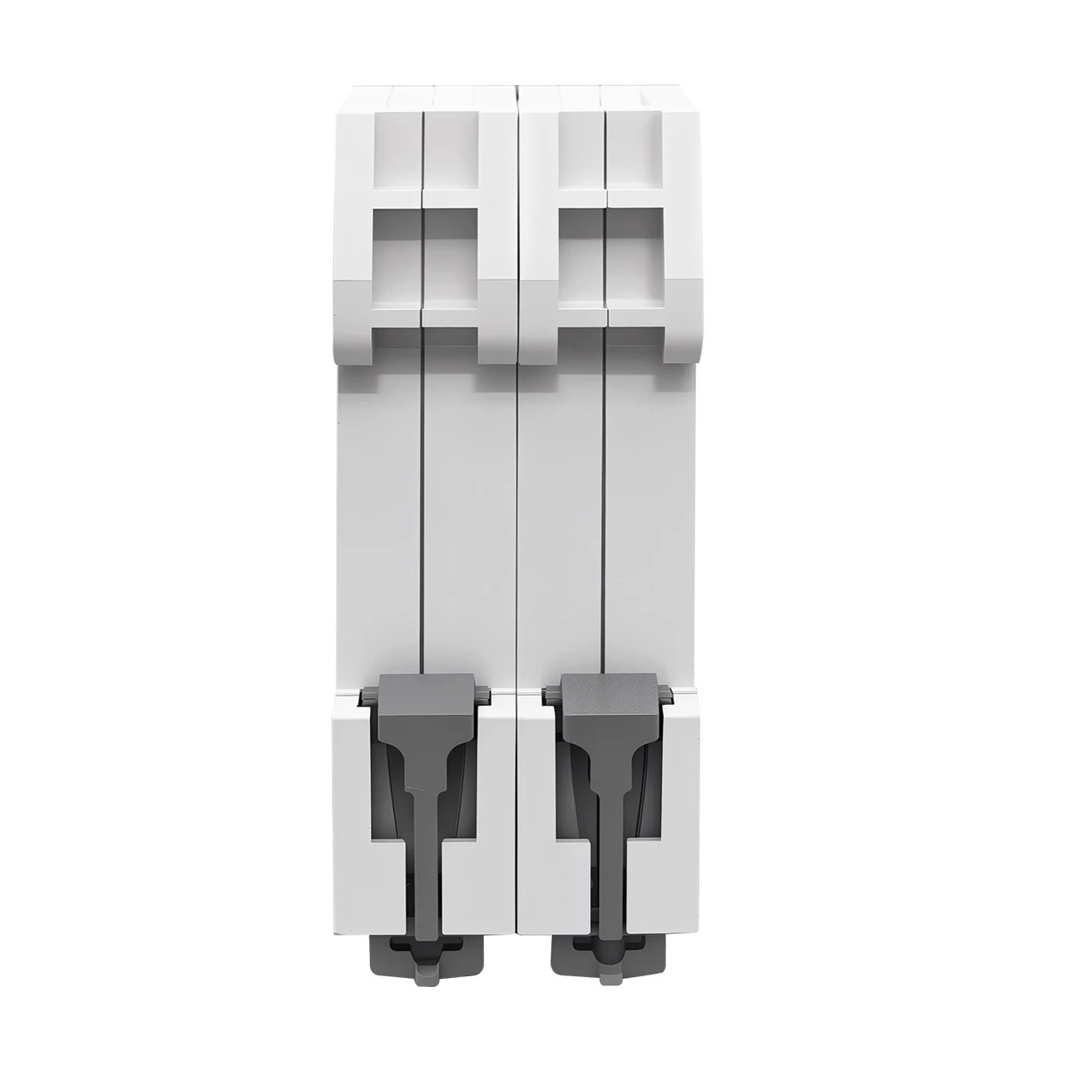
Installation uses the standard 35 mm rail: the device clips on with the spring-loaded foot at the bottom and is released with a screwdriver in the slot, so it can be fitted or removed without disturbing neighbouring modules. Two module widths keep a changeover point for a single-phase circuit inside a small part of the enclosure.
Wiring
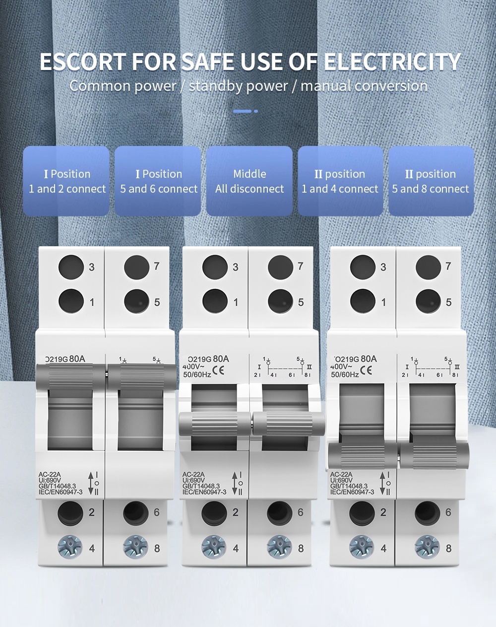
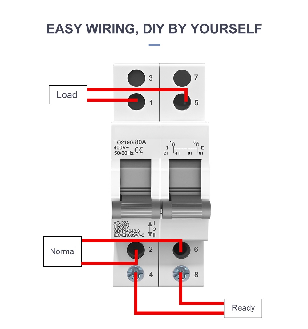
Terminal numbering follows the device: 1, 3, 5, 7 at the top and 2, 4, 6, 8 at the bottom, with the odd numbers on the line side of each pole and the even numbers on the load side. In position I the top terminals are connected to the bottom terminals of the first source; in position II they are connected to the second source; in the centre position both circuits are open.
For dual-power changeover the manufacturer specifies feeding the normal supply and the standby supply from the lower terminals and taking the load from the upper terminals, which is the arrangement drawn on the front face. With the handle at I the load is fed from the normal supply; at II it is fed from the standby supply; at OFF both paths are open and the load is isolated. The incoming and outgoing side can otherwise be arranged to suit the panel, as long as the source and load are never swapped between the two changeover paths.
Dimensions
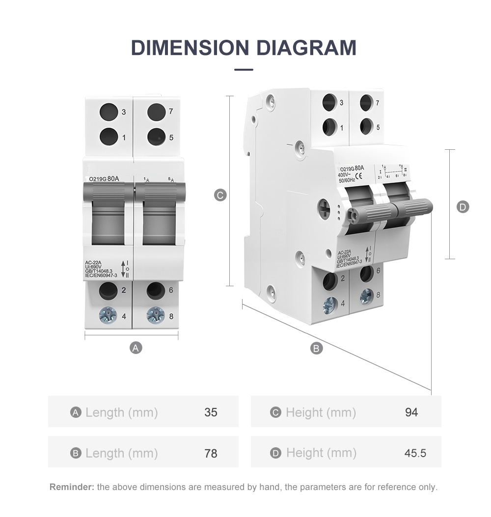
The 2P unit is 35 mm wide and 94 mm high; the depth over the handle is 78 mm and the body depth 45.5 mm, as marked A to D on the manufacturer’s drawing. Dimensions are measured by hand and are for reference — allow clearance for the handle swing and for the cable bend radius at the terminals.
Markings on the front face
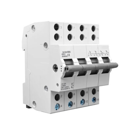
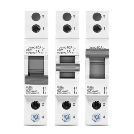
The front carries the terminal numbers 1, 3, 5, 7 at the top and 2, 4, 6, 8 at the bottom, the changeover symbol beside the handle, the model and current rating, the rated voltage and frequency, the CE mark and the standard references. The specification block on the lower half repeats the utilization category AC-22A, the insulation voltage Ui 690 V and the standard numbers, so the ratings can be read with the device installed in a panel.

Typical applications
- Manual changeover between a mains supply and a standby single-phase source, with both conductors switched.
- Isolation and source selection on small distribution and control panels.
- Load transfer where a visible, lockable disconnect position is required.
- Pumping, lighting and small machine circuits that must not be fed from two sources at once.
- Inverter or PV input changeover where neutral must not be left floating.

Manufacturing
The switch is assembled and tested on the manufacturer’s own automated calibration and test lines, with the calibration stations and the moulding shop shown below.

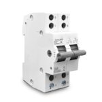
Product reference images and drawings
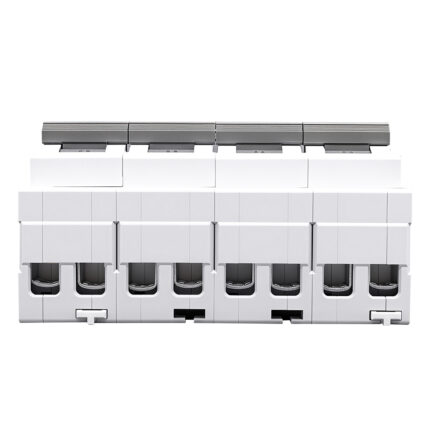
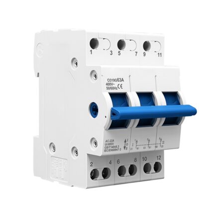
Manufacturer reference views for the O219G. Check the terminal arrangement and handle positions against the supplied unit.