






NewTrend · Weekly programmable time switch
Product overview
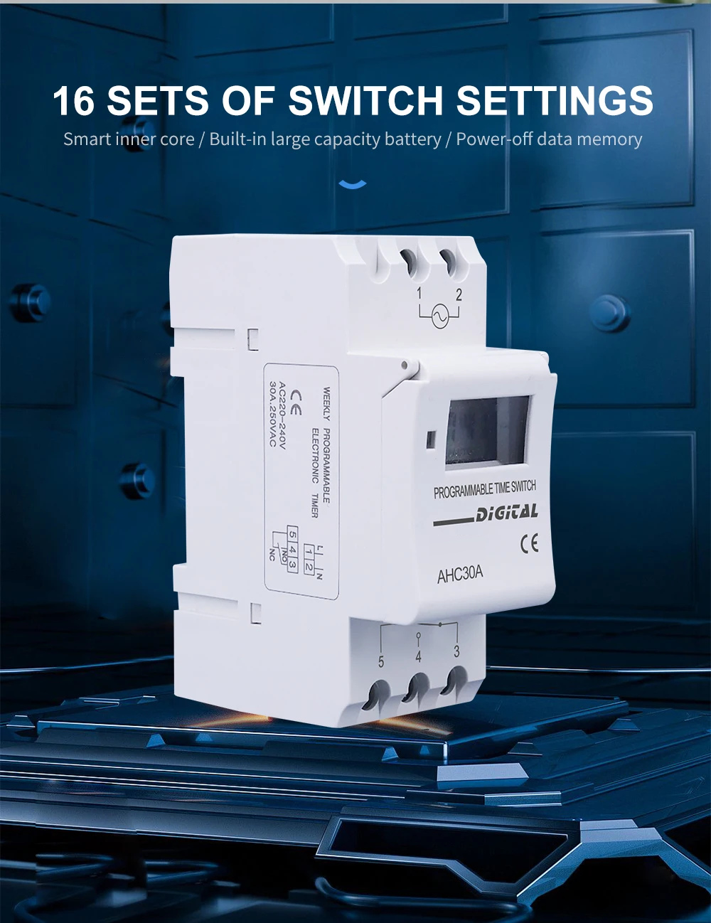
The AHC30A weekly digital time switch combines an LCD clock, 16 ON/OFF settings, manual override and battery-backed programme memory. Two photographed versions are covered on this page: a five-terminal changeover-contact version and a four-terminal version with a switched line output. Select the output type to match the intended wiring.

Technical specifications
| Model | AHC30A |
|---|---|
| Photographed supply versions | AC 220–240V |
| Photographed contact rating | 30A at 250V AC |
| Output options | Five-terminal changeover / Four-terminal direct switched-L output |
| Programming | 16 ON/OFF settings per day or week |
| Minimum setting interval | 1 minute |
| Timer range | 1 minute to 168 hours |
| Time accuracy reference | Average error: 1 second / 24 hours at 25°C |
| Written hysteresis reference | 2 seconds / day at 25°C |
| Display and local controls | LCD; P, D+, H+, M+, clock, RESET and MANUAL keys |
| Memory | Built-in rechargeable battery and power-off programme memory |
| Written reserve reference | 60 days |
| Power consumption reference | 4.5VA maximum |
| Operating temperature reference | −20°C to +50°C |
| Mounting | 35mm DIN rail |
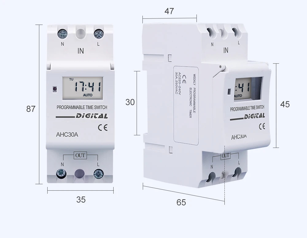
| Outline dimensions | 87 × 35 × 65mm; see applicable outline drawing |
Choose the output version
| Output type | Terminal arrangement | Connection |
|---|---|---|
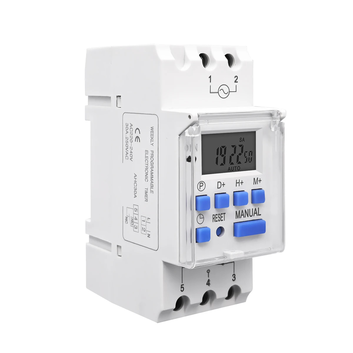
| Changeover | Supply 1–2; output 3–4–5 | Separate 1NO + 1NC changeover contact; use the five-terminal diagram. |
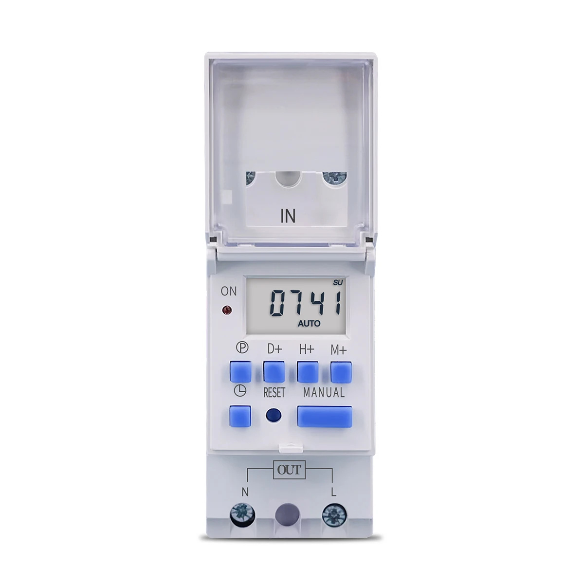
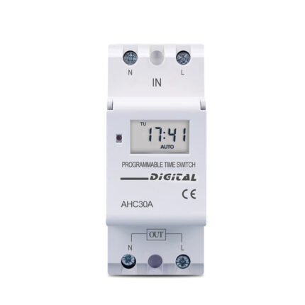
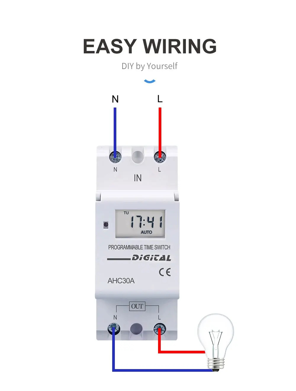
| Direct output | N/L input; N/L output | Switched line output with a neutral path; use the four-terminal diagram. |
The common source feature table calls the family a changeover switch. This applies to the five-terminal version; it must not be used as the wiring definition of the four-terminal version.

Five-terminal changeover wiring
Use terminals 1 and 2 for the timer supply and the separate output terminals 3, 4 and 5 for the changeover circuit. The illustrated connection links the line feed to the common output terminal. Follow the contact diagram of this version.

Four-terminal direct-output wiring
Connect the supply to the upper N and L input terminals and the load to the lower output terminals. The illustrated switched line and neutral connections differ from the five-terminal changeover arrangement.
Weekly scheduling and manual control
Set ON/OFF periods for selected days or a weekly cycle using the front keys. MANUAL provides local override; the display shows the current time and automatic operating state. The cover opens to expose the programming keys.

Memory and original series references
The source describes built-in rechargeable battery backup and a 60-day reserve reference. The written battery reference is 1.2V, 40mAh; the illustrated battery-chemistry wording differs, so no single chemistry is specified.
Original family supply references include 5V, 12V, 24V, 110V, 220V and 85–265V, with AC-only and AC/DC versions distinguished in the text. The shared table includes 16A/30A ratings, while both photographed AHC30A versions shown here are marked AC220–240V and 30A at 250V AC. Other combinations are not opened as selectable versions.

Dimensions and installation
The supplied outline shows 87mm overall height, 35mm width and 65mm depth, plus 47mm, 45mm and 30mm housing references. Check the selected output version and its terminal arrangement when planning the panel.
Applications and supplied items
Illustrated uses include lighting, water heaters, automation, solar installations and gate control. The original package description includes a digital timer and an English manual. Match the selected output contact duty to the connected load.