

NewTrend · Mechanical timer switch
Product overview
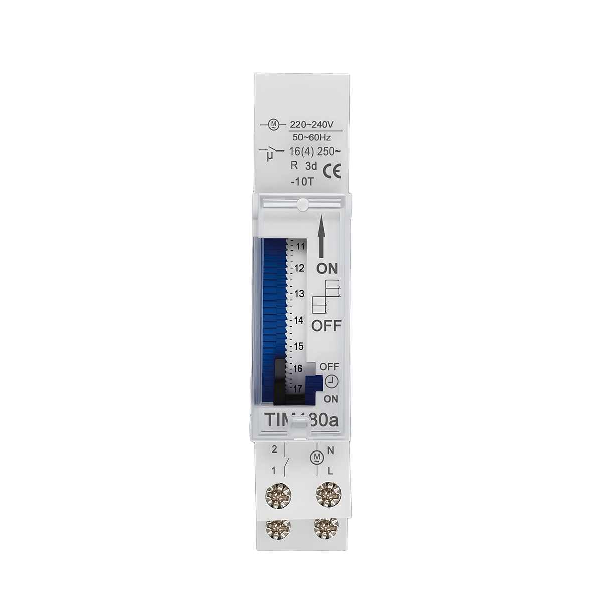
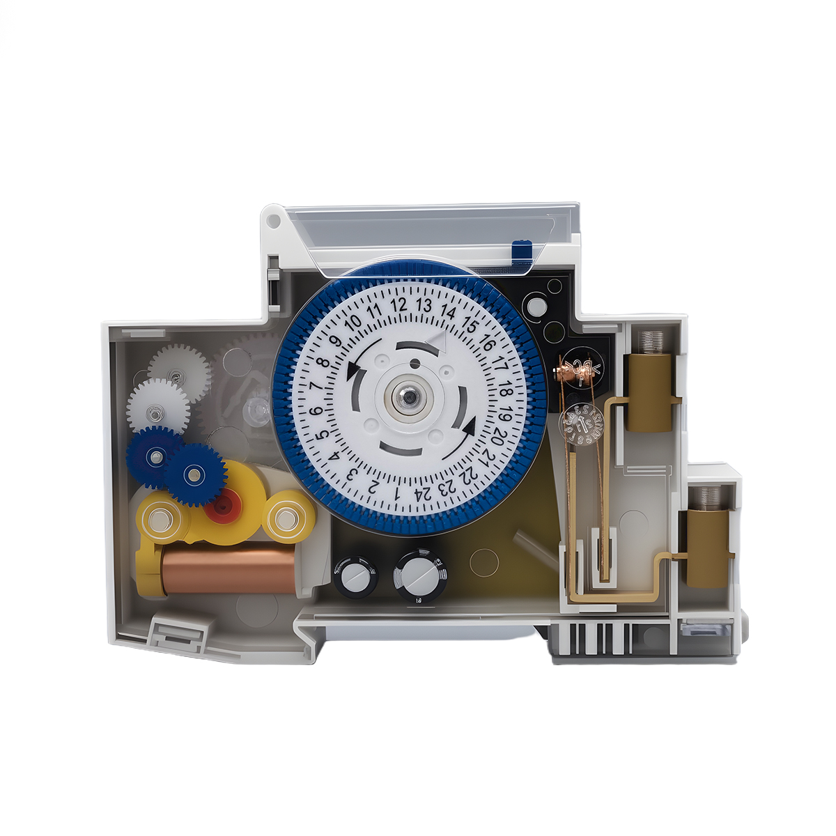
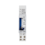
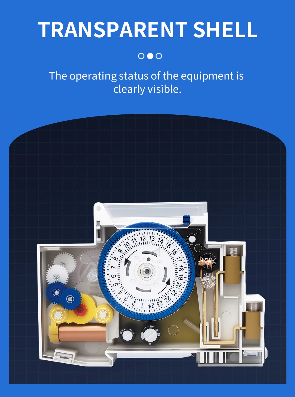
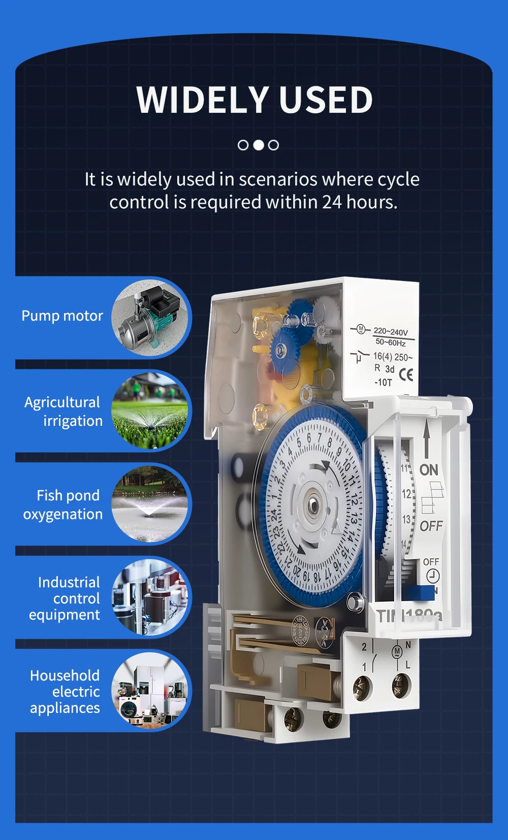
The TIM180a is an 18 mm DIN-rail mechanical time switch for daily automatic switching. The 24-hour programme uses 15-minute segments, with AUTO, constant ON and constant OFF operation. A transparent side panel reveals the timing mechanism, and a built-in battery provides timekeeping backup.
Key features
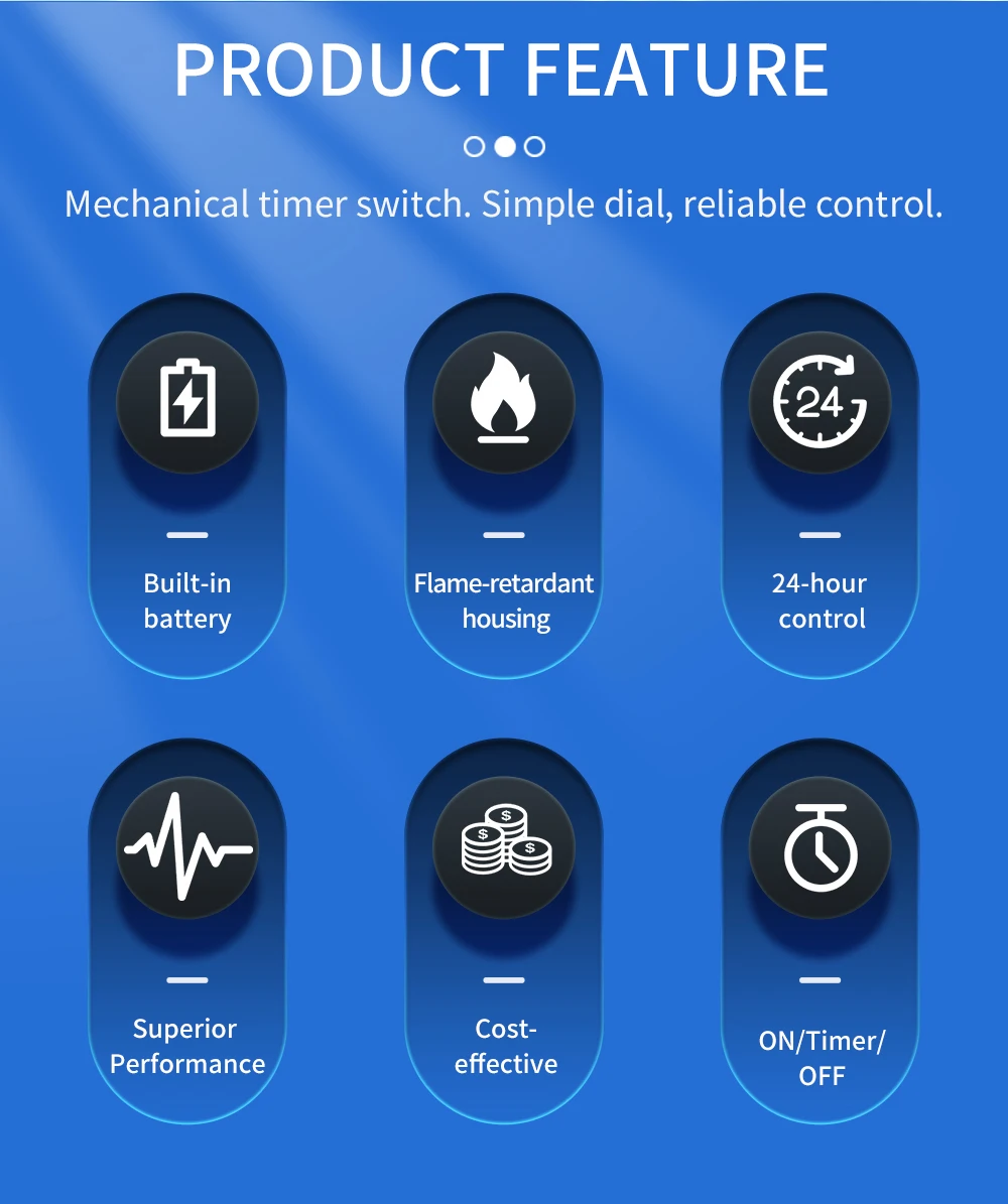
- Daily 24-hour mechanical programme with 15-minute switching segments.
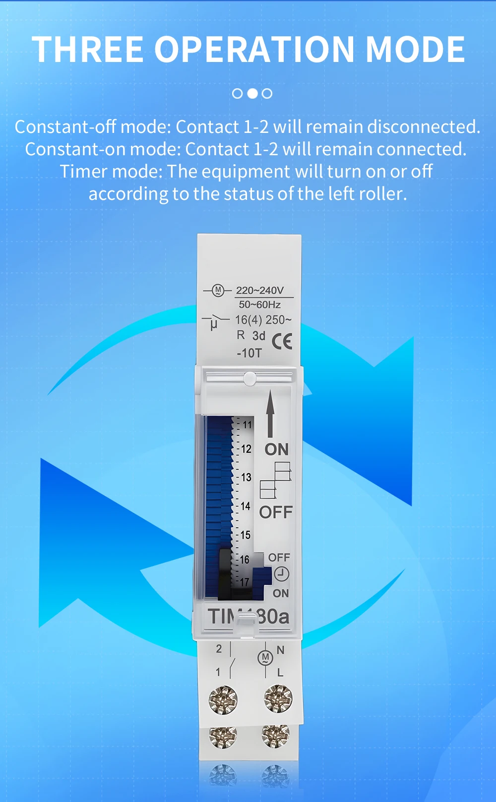
- Three operating modes: timed AUTO, constant ON and constant OFF.
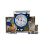
- Transparent side housing for viewing the timing mechanism.
- Flame-retardant housing and DIN-rail installation.
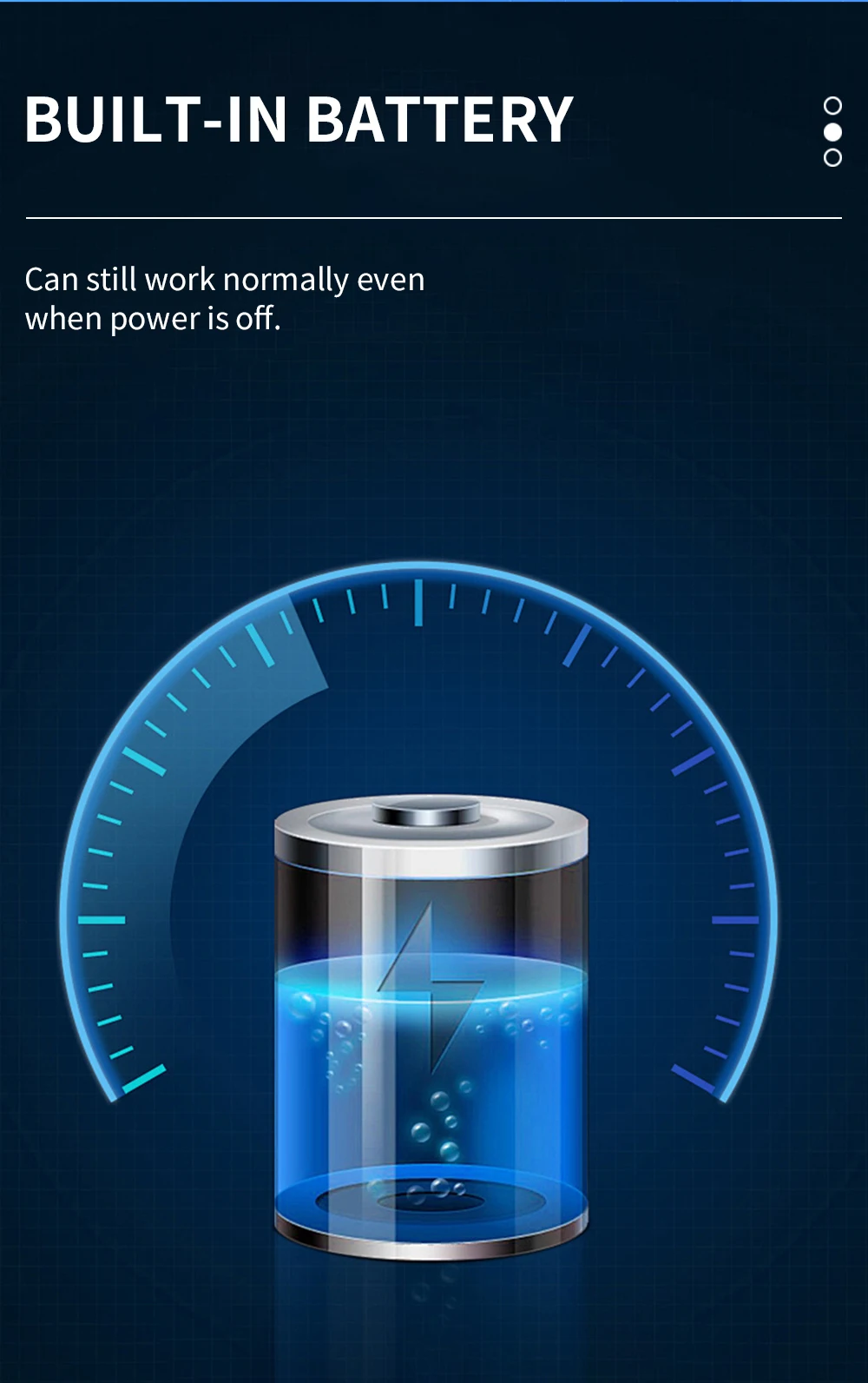
- Built-in battery for timekeeping during a power outage.
Transparent housing and mechanism
Technical selection summary
| Model | TIM180a |
|---|---|
| Time programme | 24-hour cycle |
| Minimum switching interval | 15 minutes |
| Module width | 18 mm |
| Supply voltage options | AC 90–121 V; AC 200–264 V |
| Rated current | 15 A |
| Contact marking | 16(4) A, 250 V AC |
| Frequency (AC 220–240 V version) | 50/60 Hz |
| Operating modes | AUTO / Constant ON / Constant OFF |
| Time accuracy | ±3 seconds/day at 22°C |
| Operating temperature | −10°C to +50°C |
| Terminal conductor capacity | 2 × 2.5 mm² |
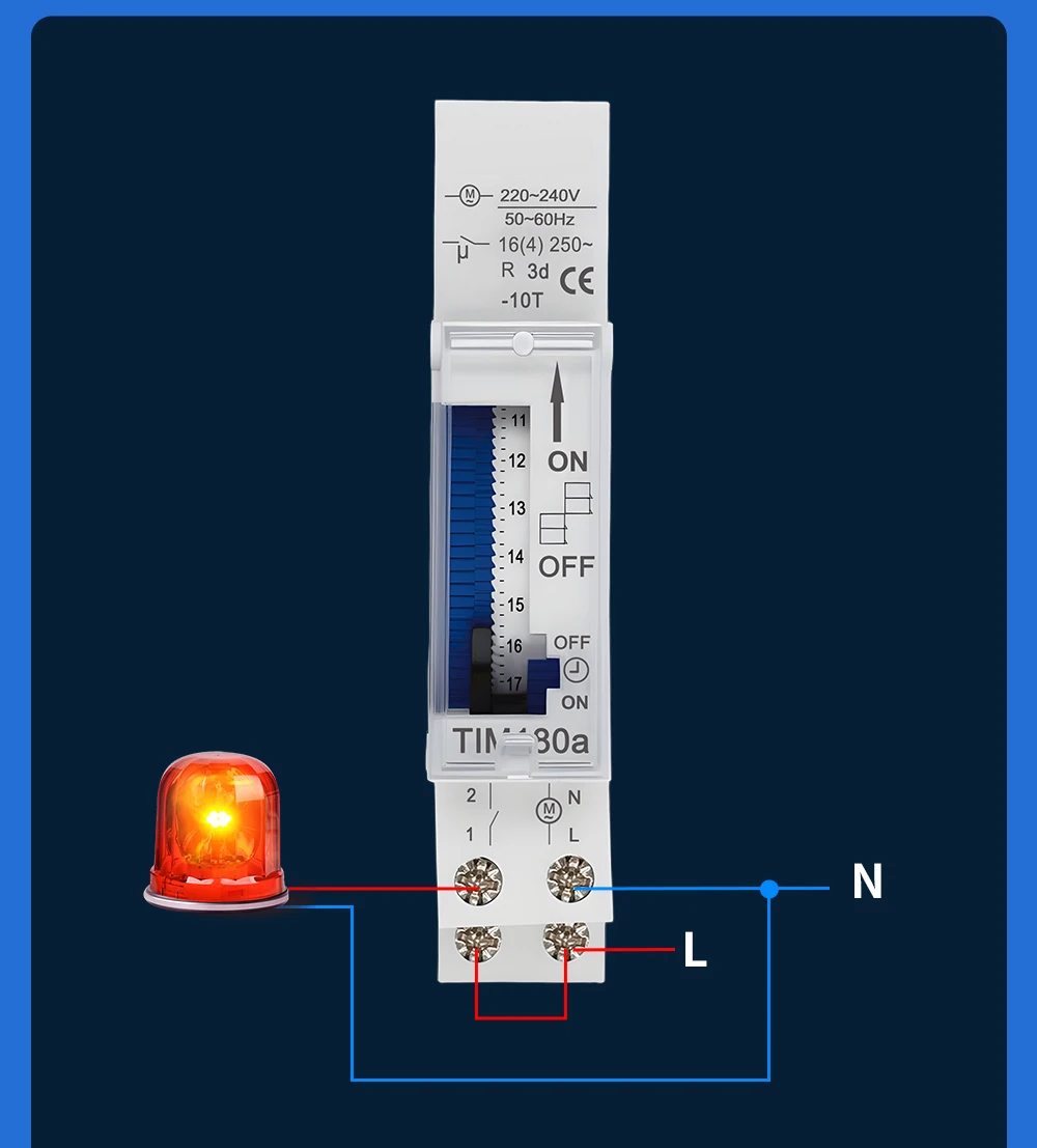
| Output terminals | 1–2 |
| Power supply terminals | L–N |
| Power reserve | Built-in battery |
| Housing | Transparent side panel |
| Mounting | DIN rail |
Typical applications
- Pump timing and agricultural irrigation.
- Fish-pond oxygenation schedules.
- Industrial control equipment with daily switching requirements.
- Household electrical appliances, lighting, ventilation and heating schedules.
Operation
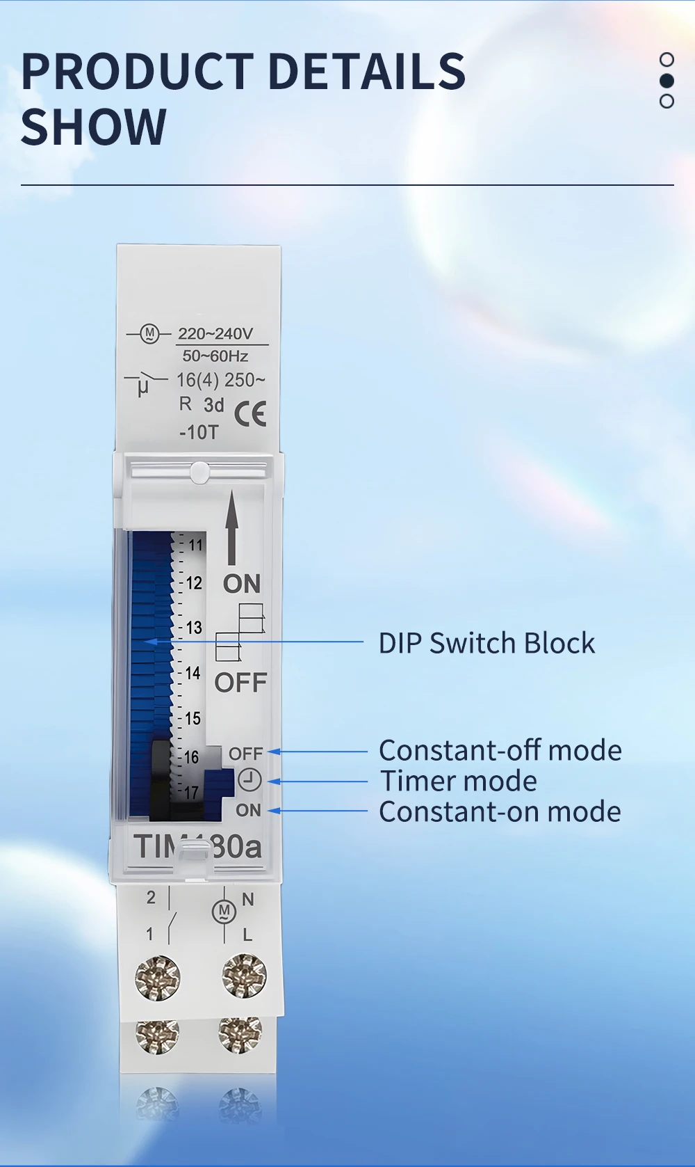
Move the switching segments to the right for OFF or to the left for ON. Each segment represents 15 minutes within the daily 24-hour programme.
| Constant OFF | Contact 1–2 remains open. |
|---|---|
| AUTO / Timer | Contact 1–2 switches according to the programmed segments. |
| Constant ON | Contact 1–2 remains closed. |
Three operating modes
Battery and maintenance
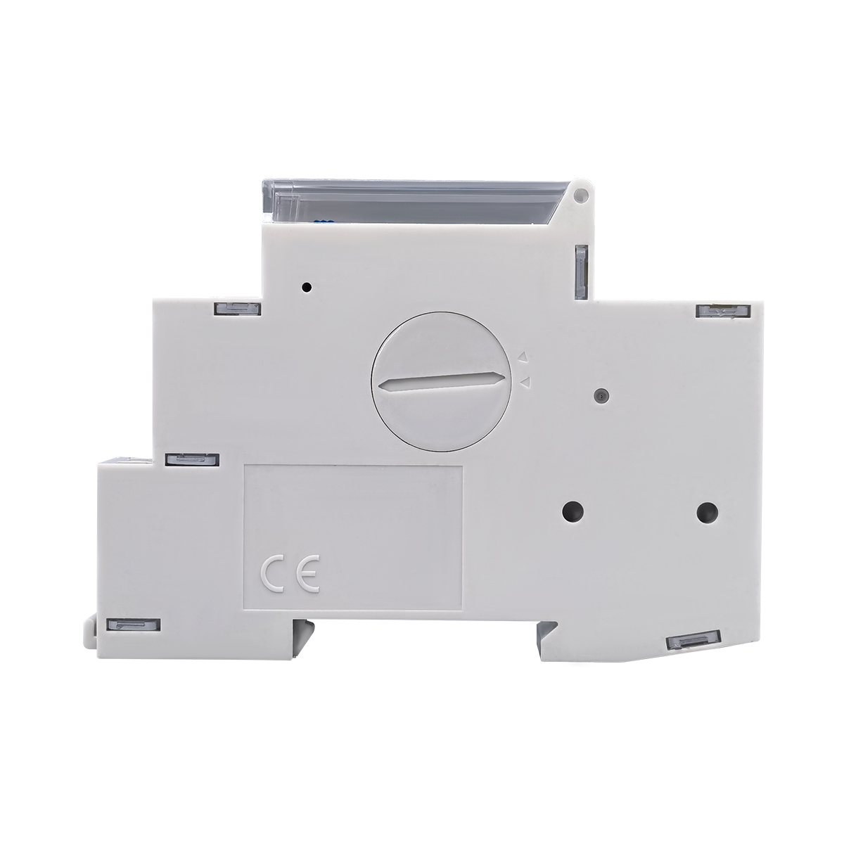
The built-in battery maintains the timer mechanism during a power outage. Power reserve supports timekeeping; it does not supply the connected load.
- Isolate the power supply before maintenance.
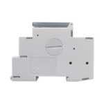
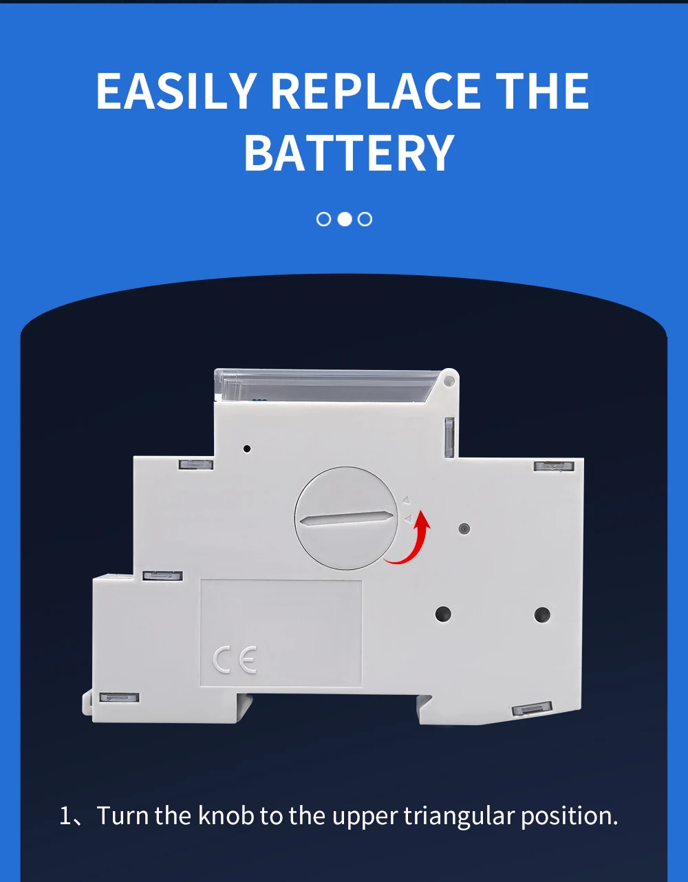
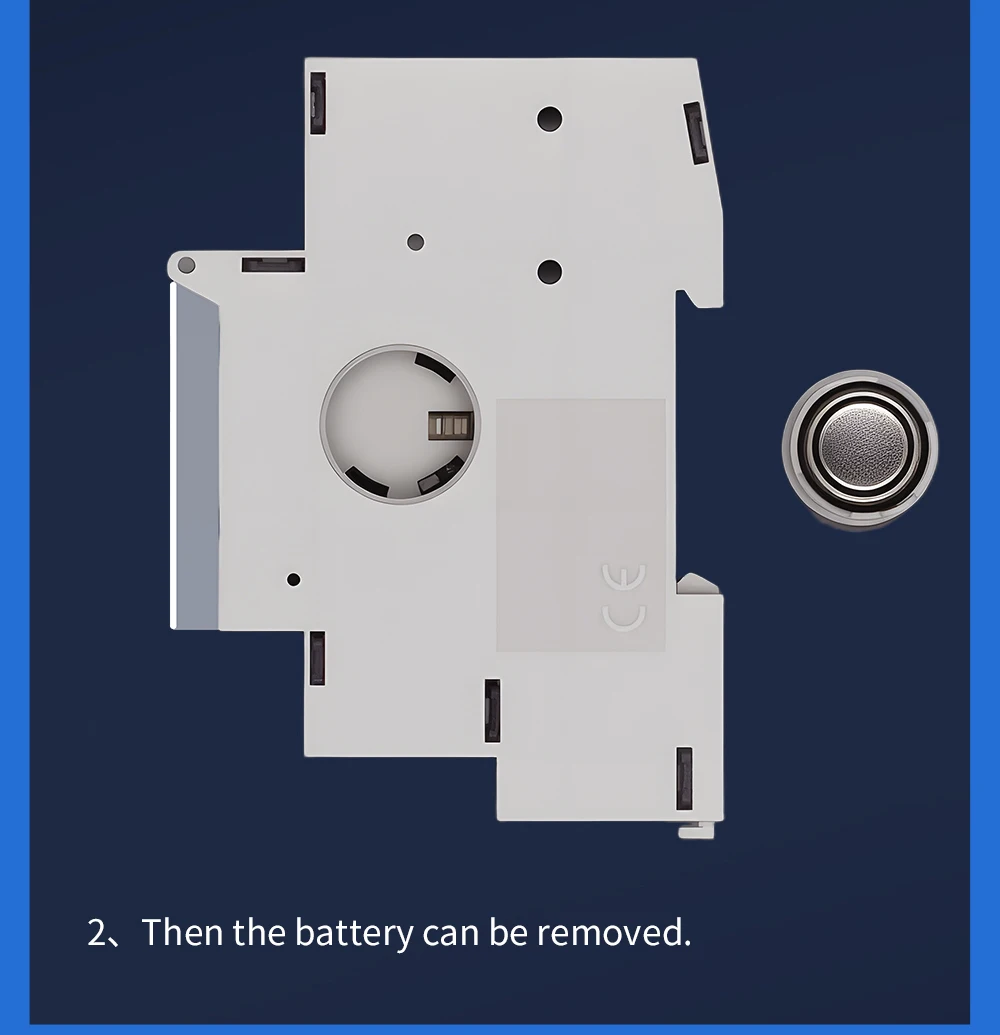
- Turn the side battery-cover knob towards the upper triangular position.
- Open the cover to remove the battery, as illustrated below.
Battery replacement
Installation
Install the timer in an electrical cabinet on a DIN rail. Keep it away from strong interference sources, use appropriate protective measures and check compatibility with the controlled equipment. Use a suitably rated contactor when the load requires one; the two wiring illustrations show direct-load and contactor-control arrangements.
Direct load wiring
Wiring with an external contactor