



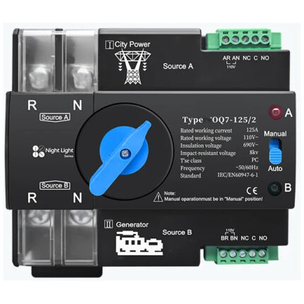

NewTrend · dual power automatic transfer switch
Product overview
The OQ5-125A/4P, also written OQ5-125/4P, is the 125 A four-pole member of the manufacturer’s OQ5 63/100/125 A DIN-rail automatic transfer family. It is intended for utility and generator sources. The manufacturer’s common photographs show the 100 A version; those original markings remain unchanged.

Technical selection summary
| Model labels | OQ5-125A/4P / OQ5-125/4P |
|---|---|
| Offered rated current | 125 A, explicitly listed in manufacturer family text |
| Poles | 4P, three-phase four-wire arrangement |
| Source A | Utility / city power |
| Source B | Generator / alternate source |
| Control/supply reference | L+N AC 220–230 V, 50/60 Hz; source family table writes 3×220 / 3×230 V |
| Insulation voltage | 690 V AC, illustrated nameplate |
| Impulse withstand | 8 kV, illustrated nameplate |
| Class | PC |
| Transfer time | <8 ms, source reference; not a zero-time transfer claim |
| Modes | Manual / automatic |
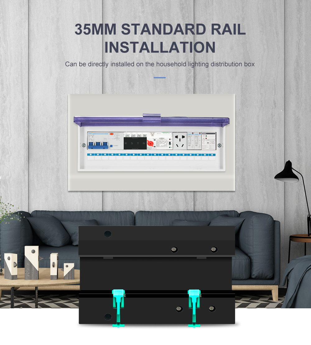
| Mounting | 35 mm DIN rail |
| Standard marking | IEC/EN60947-6-1 |
| Application restriction | Not for PV systems and inverters |
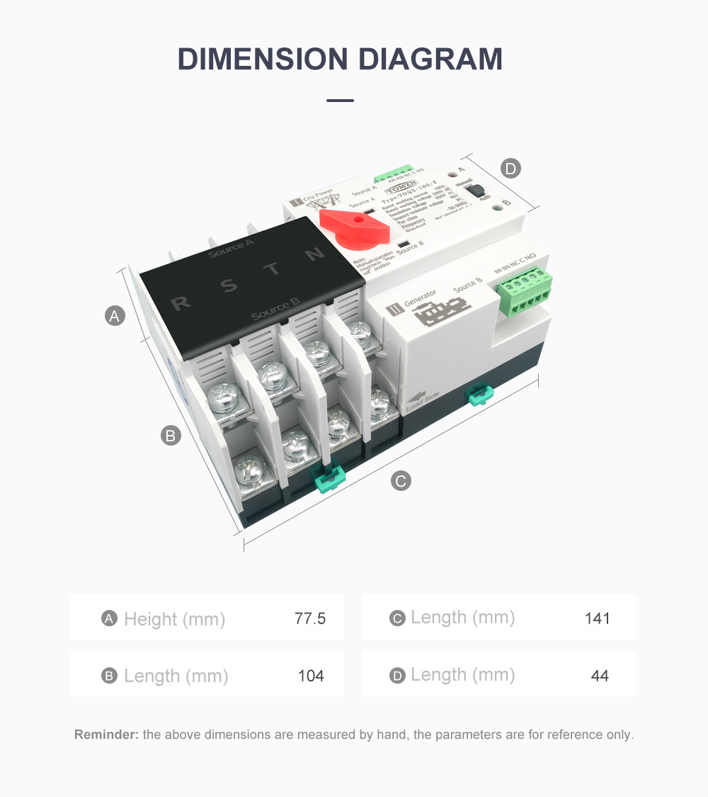
| Family outline reference | 77.5, 104, 141 and 44 mm references in original drawing; confirm the supplied 125 A frame |
Utility and generator source arrangement
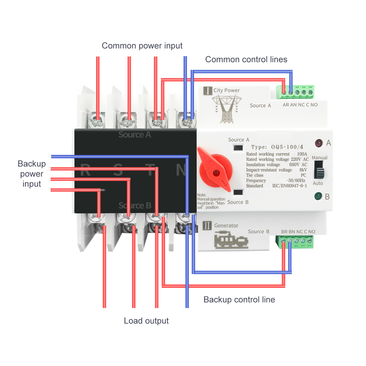
This version is for city power and generator changeover. The manufacturer explicitly excludes photovoltaic systems and inverters. Connect the power circuits and both control-line groups as marked on the device.
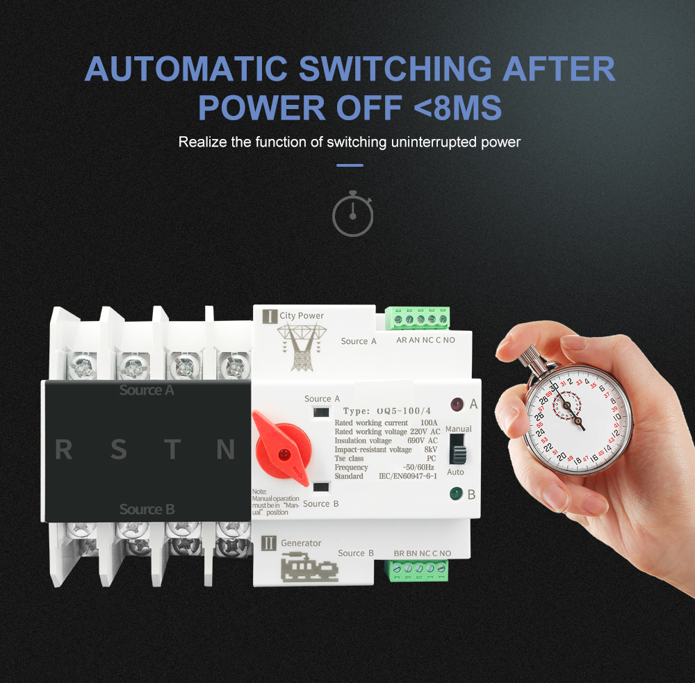
Automatic transfer reference
The manufacturer states switching in less than 8 ms. The finite transfer time is retained instead of claiming zero-break power. Generator starting/stopping capability is not established by this source.
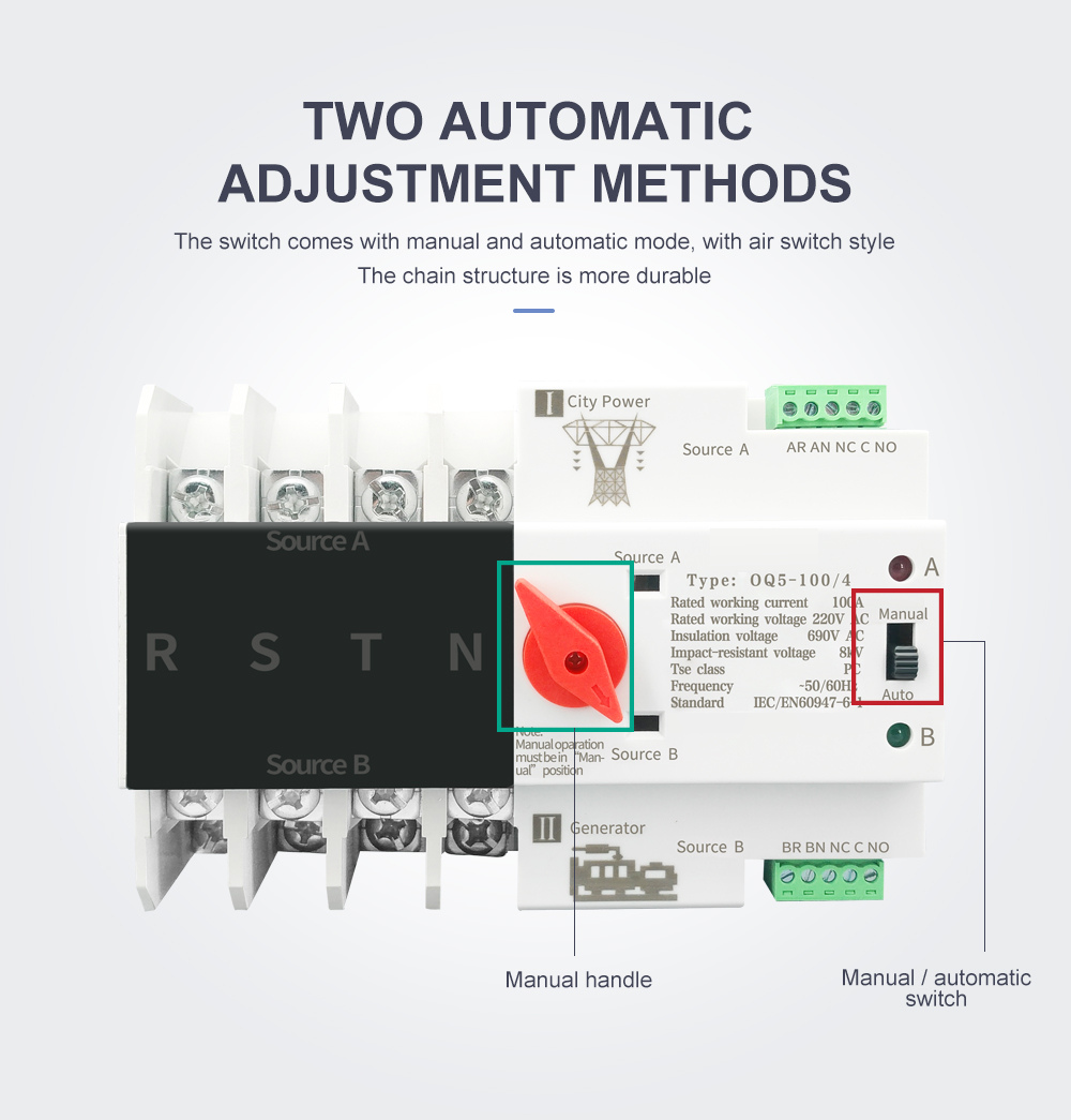
Manual and automatic operation
Select manual mode before operating the manual handle. The mode selector is separate from the source-selection handle.
DIN-rail installation
The rear mounting arrangement uses a 35 mm rail. Leave working space for terminals and control connectors.
Terminal construction
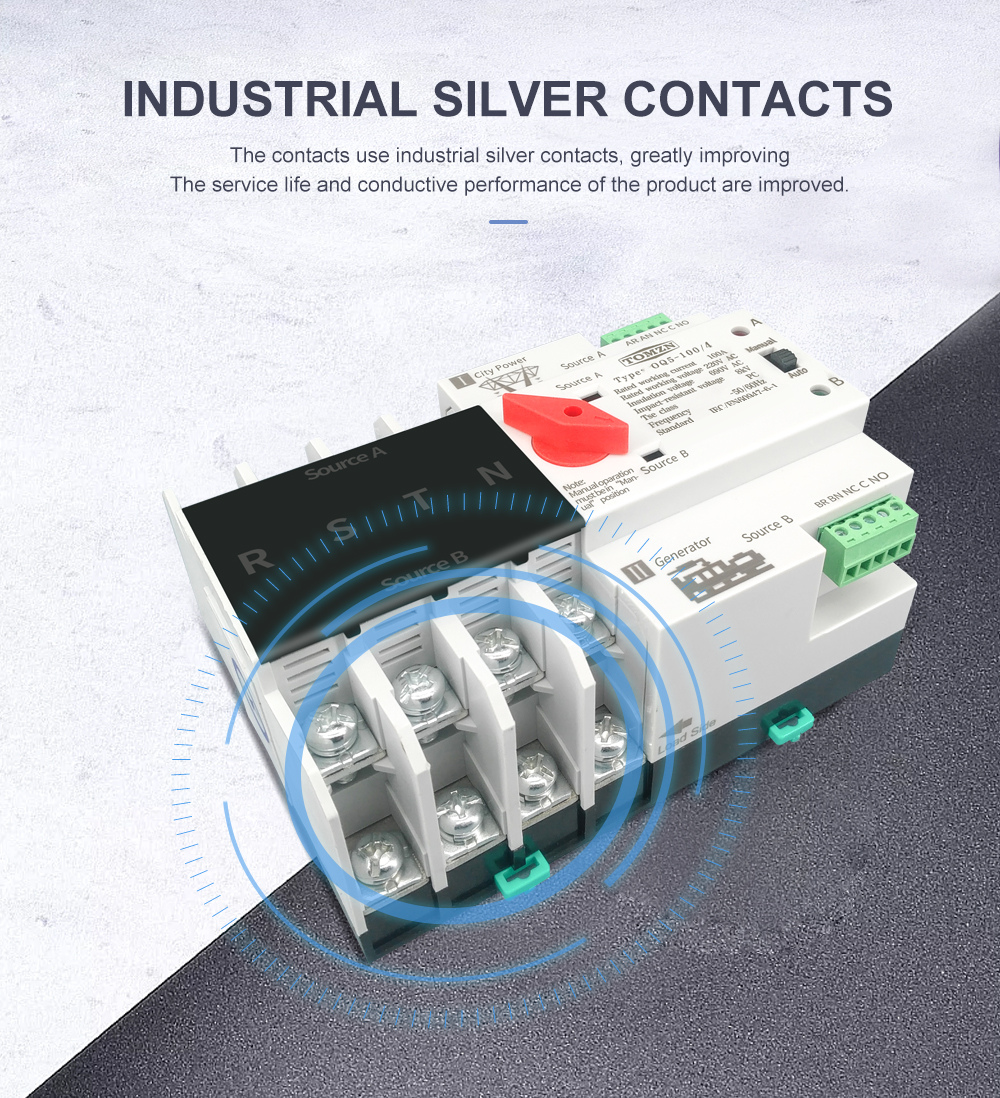
The original contact and terminal illustration shows the power-conductor connection arrangement and the terminal cover.
Wiring
The original four-pole drawing identifies common power, reserve power, control lines and load output. Follow the supplied unit diagram and terminal markings.

Original family table
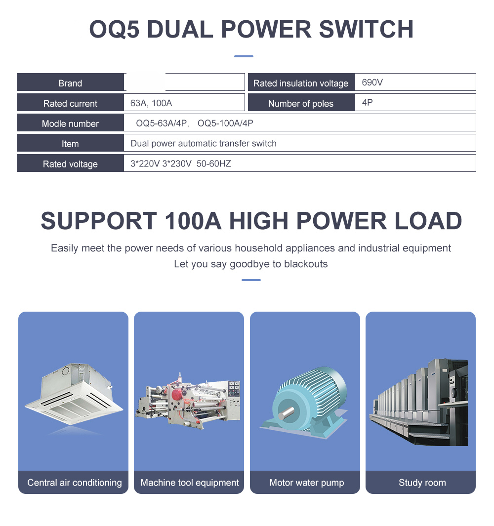
The source table below illustrates the 63 and 100 A versions, while the manufacturer’s written family list additionally names OQ5-125/4P. The 125 A selection is based on that explicit family list, not by changing the 100 A photo or table.
Dimensions
The original family drawing retains its face and side references and manual-measurement note. Confirm enclosure fit against the supplied 125 A unit.