



NewTrend · three-phase panel instrumentation
Product overview
The OEM-05 and OEM-06 panel multimeters measure three-phase voltage, three-phase current and frequency. Both provide maximum/minimum voltage and current review and maximum current demand. Select the display layout and 72×72mm or 96×96mm panel frame. This page covers the illustrated AC450V/5A input version with an AC/DC85–265V auxiliary supply.
Technical selection summary
| Models | OEM-05 and OEM-06 |
|---|---|
| Quantities | Three-phase voltage, three-phase current and frequency |
| Illustrated voltage / current inputs | AC 450 V / 5 A; use external instrument transformers where required |
| Auxiliary supply — selected version | AC/DC 85–265 V |
| Network configuration | Three-phase four-wire or three-phase three-wire, programmable |
| Frequency | 45–65 Hz; derived from L1 voltage signal |
| Accuracy | Class 0.5 |
| Sampling rate | 1.5 readings per second |
| Input consumption | Less than 0.5 VA per phase |
| Continuous overload capability | 1.2 × measuring input |
| Display resolution | Voltage 0.1 V; current 0.001 A; frequency 0.01 Hz |
| Recorded values | Maximum and minimum voltage/current; maximum current demand |
| Demand interval | 5–60 minutes, with 1-minute sliding interval |
| Voltage display cycling | 1.0–10.0 seconds |
| PT setting | 1.0–3200.0; set 1.0 for direct voltage input |
| CT primary-current setting | 5–9995 A for a /5 A CT; set the CT primary rating |
| Programming code | Factory default 0; programmable 0–9999 |
| 72 mm frame | Front 72 × 72 mm; case 67 × 67 × 53 mm; panel opening 68 × 68 mm |
| 96 mm frame | Front 96 × 96 mm; case 91 × 91 × 53 mm; panel opening 92 × 92 mm |
| Operating environment | −10°C to +50°C; humidity below 85% RH; free of corrosive gas |
Two display layouts
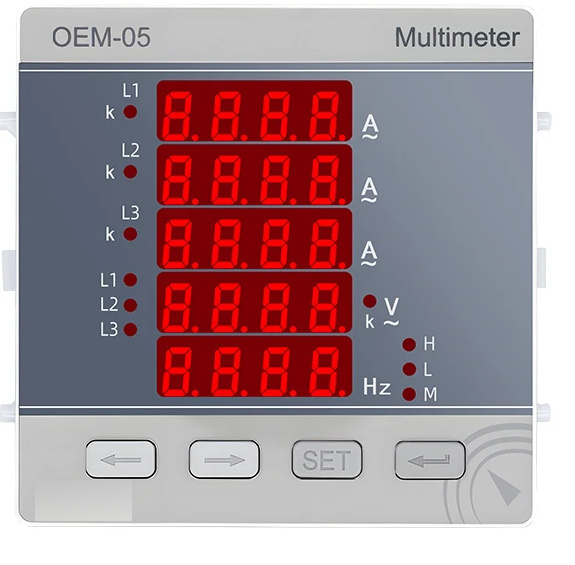
OEM-06 uses separate three-row voltage and current fields, with voltage/frequency display switching. OEM-05 places the three current readings above the selectable voltage and frequency fields. Phase and unit indicators identify the active values. Both layouts support review of saved extrema and current demand.
Voltage, current and auxiliary connections
Connect the auxiliary supply at terminals 1 and 2. The voltage terminals are VN at 14, VL1 at 11, VL2 at 12 and VL3 at 13. Current inputs use terminal pairs 4–5, 6–7 and 8–9 for IL1, IL2 and IL3. Follow the diagrams for direct voltage input, PT voltage input and external CT current input. Select n3.4 for three-phase four-wire or n3.3 for three-phase three-wire. Frequency is acquired from L1 voltage; it is not displayed when that signal is absent.

Use correctly rated instrument transformers when the measured circuit exceeds the meter input rating. Maintain phase sequence and CT polarity. Isolate the circuit before installation and never open an energised CT secondary.
Front keys and stored values
From the real-time screen, the SET key steps through minimum and maximum voltage/current and maximum current demand. Hold SET for two seconds to enter the programming-code screen; the factory code is 0. In the programming menu, SET selects or stores the active value. The return key moves back; the arrow keys move the cursor or decrease/increase the selected value. With no key operation for 120 seconds, the meter returns to the real-time display.
The voltage-display key changes the voltage/frequency view. Hold it for two seconds to switch between fixed and cyclic voltage display. The cycling interval is adjustable from 1.0 to 10.0 seconds.

Programming the installation
Set the network mode before use. For direct voltage measurement, set Pt to 1.0; when a PT is fitted, use its primary-to-secondary ratio. For a /5A CT, enter the primary-current rating: a 100A/5A CT uses a Ct setting of 100, while direct 5A input uses 5. Select the demand interval between 5 and 60 minutes; the sliding interval is one minute.
The rSt.L item resets the stored maximum/minimum values when YES is confirmed. CLr.d clears maximum current demand. The inP codE item changes the programming code between 0 and 9999. Record a changed code for future configuration.

Panel mounting and frame selection
The 72×72mm front uses a 68×68mm panel opening; the 96×96mm front uses a 92×92mm opening. Case depth is 53mm. Fit the meter from the front and secure the retaining clips from the rear. Leave clearance for terminals, insulation and wiring access.

Typical applications
- Three-phase distribution and equipment-panel indication.
- Local review of voltage/current extremes and peak current demand.
- Transformer-connected three-phase supply monitoring within the specified input ratings.