




CNC Electric · YCC8DC
Product overview
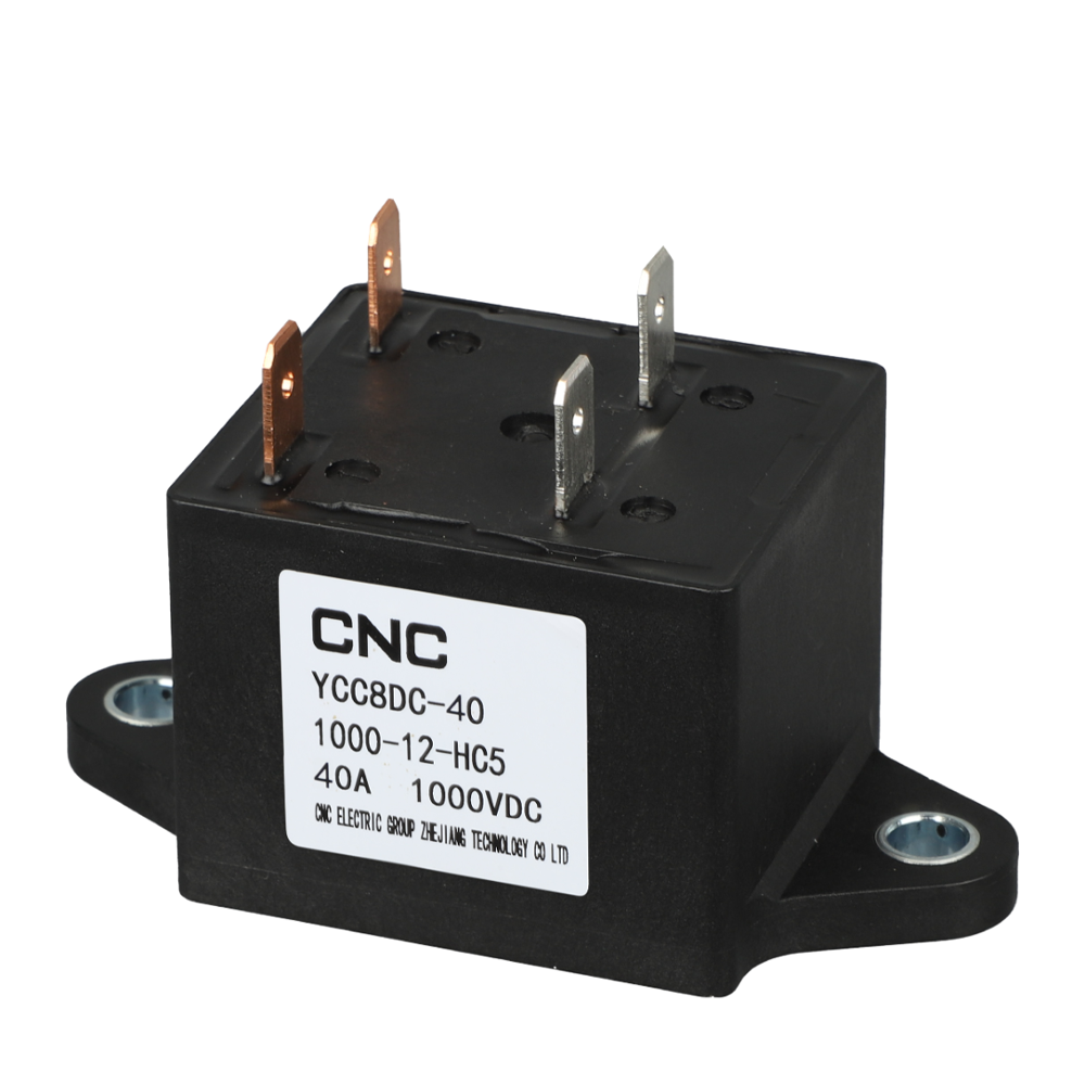
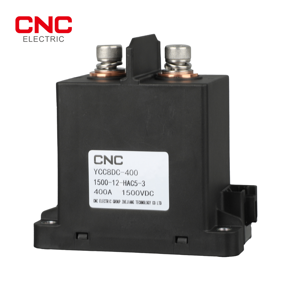
The YCC8DC contactor switches high-voltage DC loads in energy-storage, photovoltaic and DC distribution equipment. This page covers the requested YCC8DC-40, YCC8DC-200, YCC8DC-400, YCC8DC-600 and YCC8DC-1000 models with a single normally open main contact and non-polarized load terminals.
Technical selection summary
| Brand | CNC Electric |
|---|---|
| Main contact | Single pole, normally open; non-polarized load terminals |
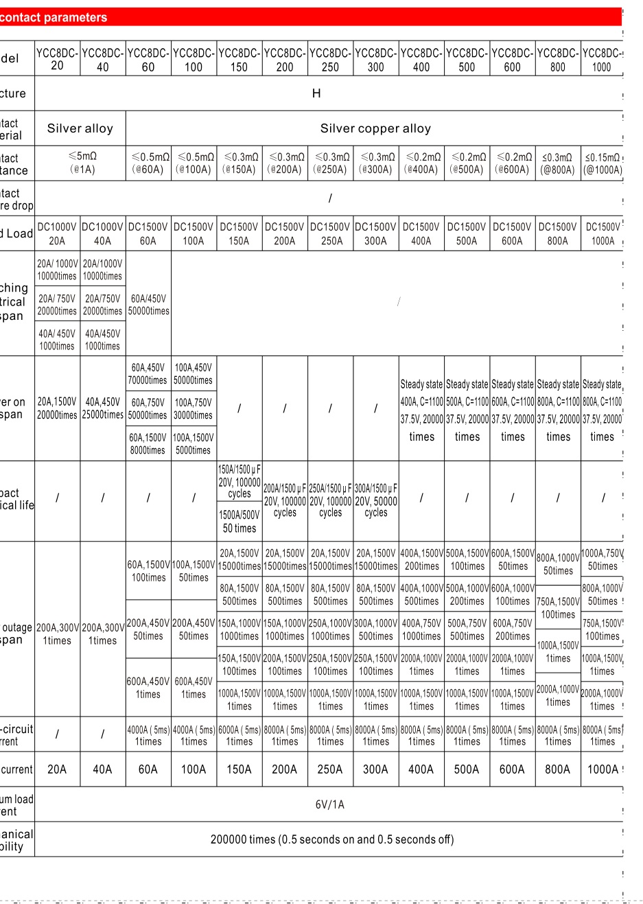
| YCC8DC-40 | 40A at DC1000V; silver-alloy contact; contact resistance ≤5mΩ at 1A |
| YCC8DC-200 | 200A at DC1500V; silver-copper-alloy contact; ≤0.3mΩ at 200A |
| YCC8DC-400 | 400A at DC1500V; silver-copper-alloy contact; ≤0.2mΩ at 400A |
| YCC8DC-600 | 600A at DC1500V; silver-copper-alloy contact; ≤0.2mΩ at 600A |
| YCC8DC-1000 | 1000A at DC1500V; silver-copper-alloy contact; ≤0.15mΩ at 1000A |
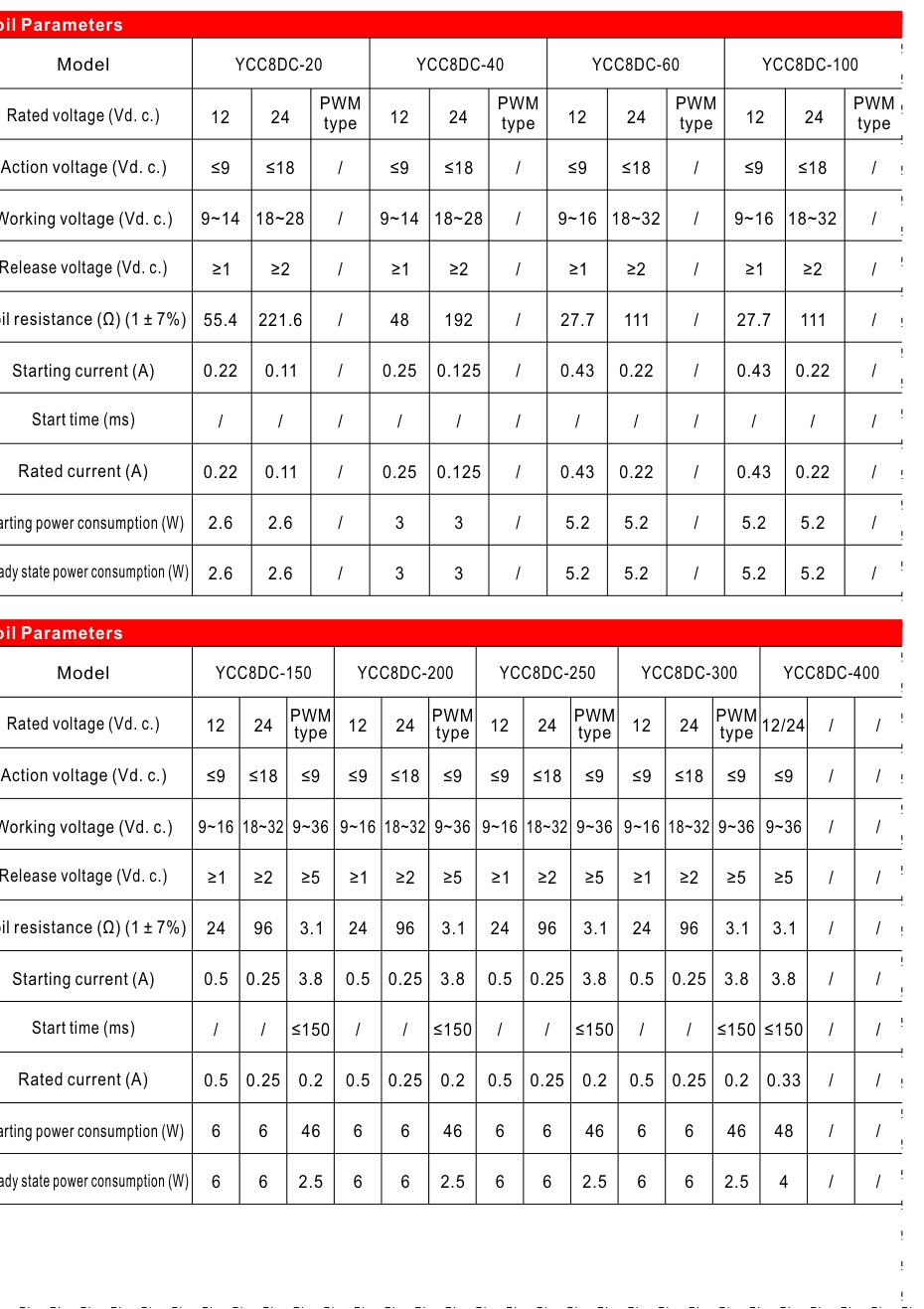
| 40A coil | DC12V: 9–14V operating range, 48Ω, 0.25A; DC24V: 18–28V, 192Ω, 0.125A; 3W |
| 200A coil | DC12V / DC24V conventional coil: 6W; PWM version operates at DC9–36V, 46W starting / 2.5W holding |
| 400A / 600A / 1000A coil | PWM input DC9–36V, nominal DC12/24V; starting 48W and 3.8A for ≤150ms; holding 4W and 0.33A |
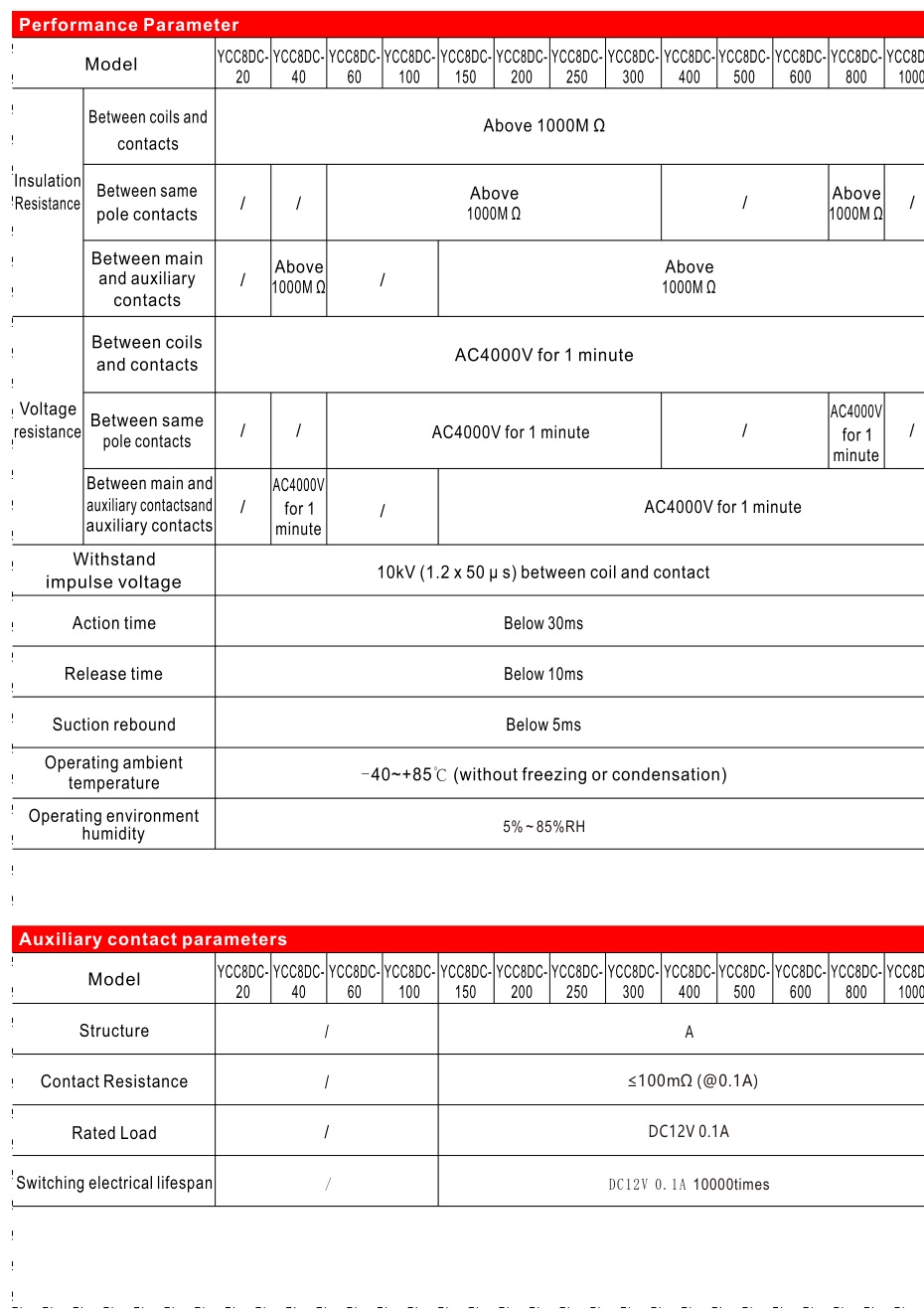
| Auxiliary contacts | 200A / 400A / 600A / 1000A: 1NO, DC12V 0.1A; ≤100mΩ at 0.1A; 40A: no auxiliary contact declared |
| Short-circuit withstand | 200A / 400A / 600A / 1000A: 8000A for 5ms, one operation; not declared for 40A |
| Mechanical endurance | 200,000 operations; 0.5s energized / 0.5s de-energized |
| Minimum switching load | 6V, 1A |
| Environment | −40 to +85°C; 5–85% RH; altitude ≤4000m |
| Ingress protection | IP67 internal cavity |
| Shock / vibration | 20G operational stability, 50G strength; 10–200Hz at 5G |
Selection and installation
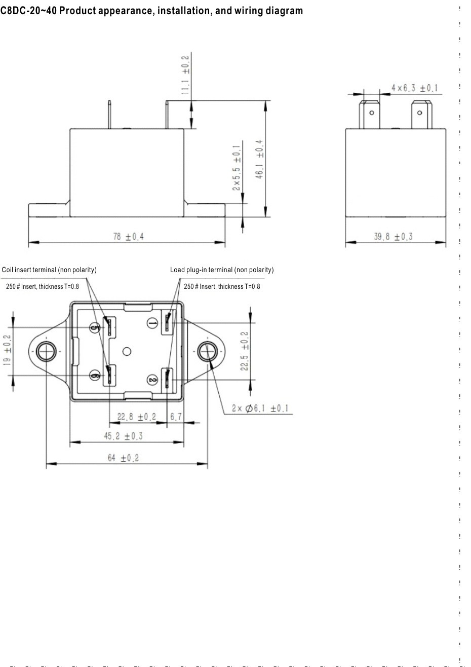
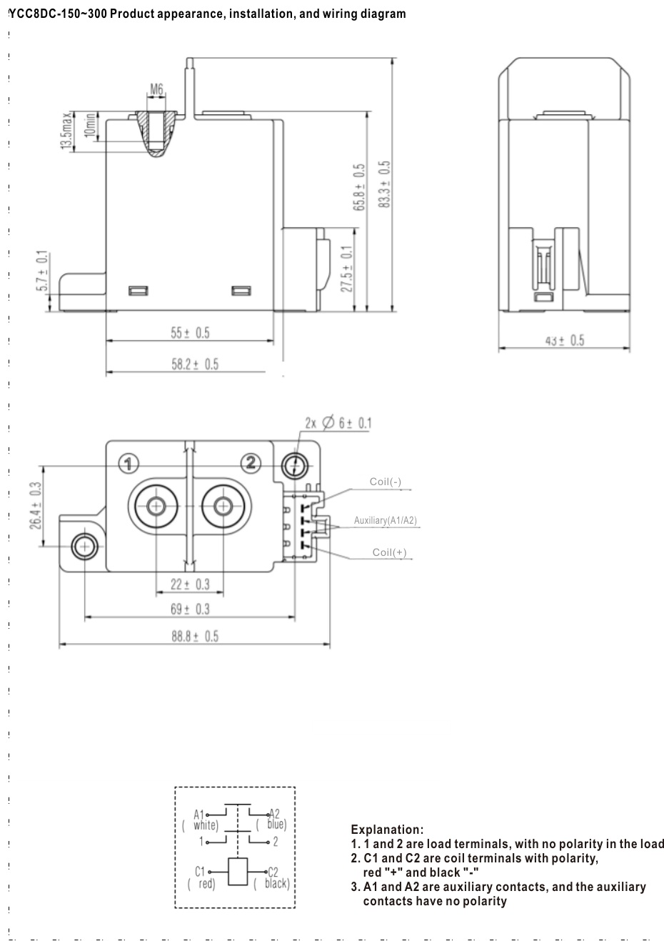
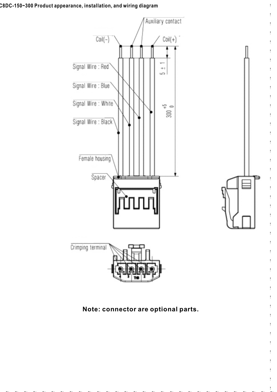
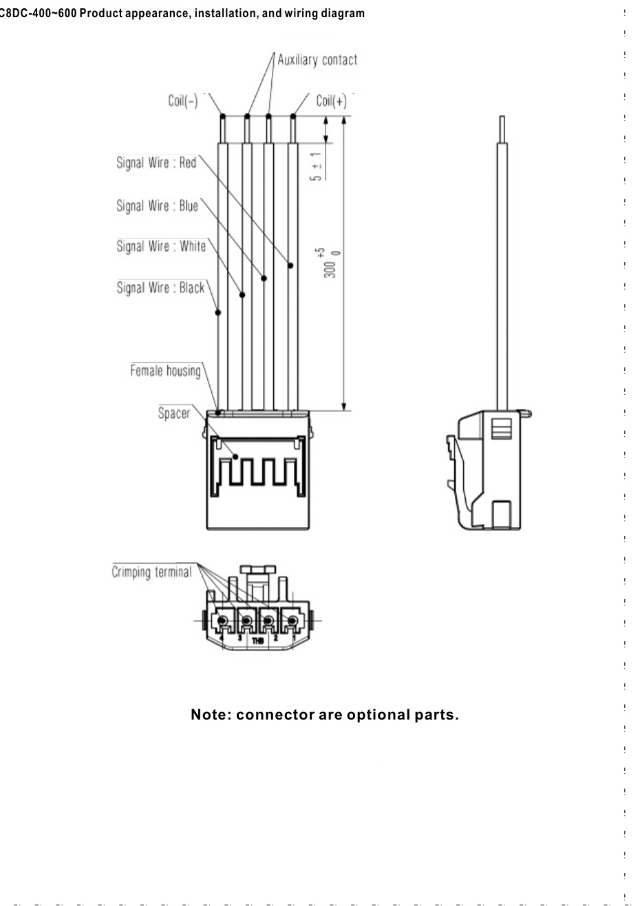
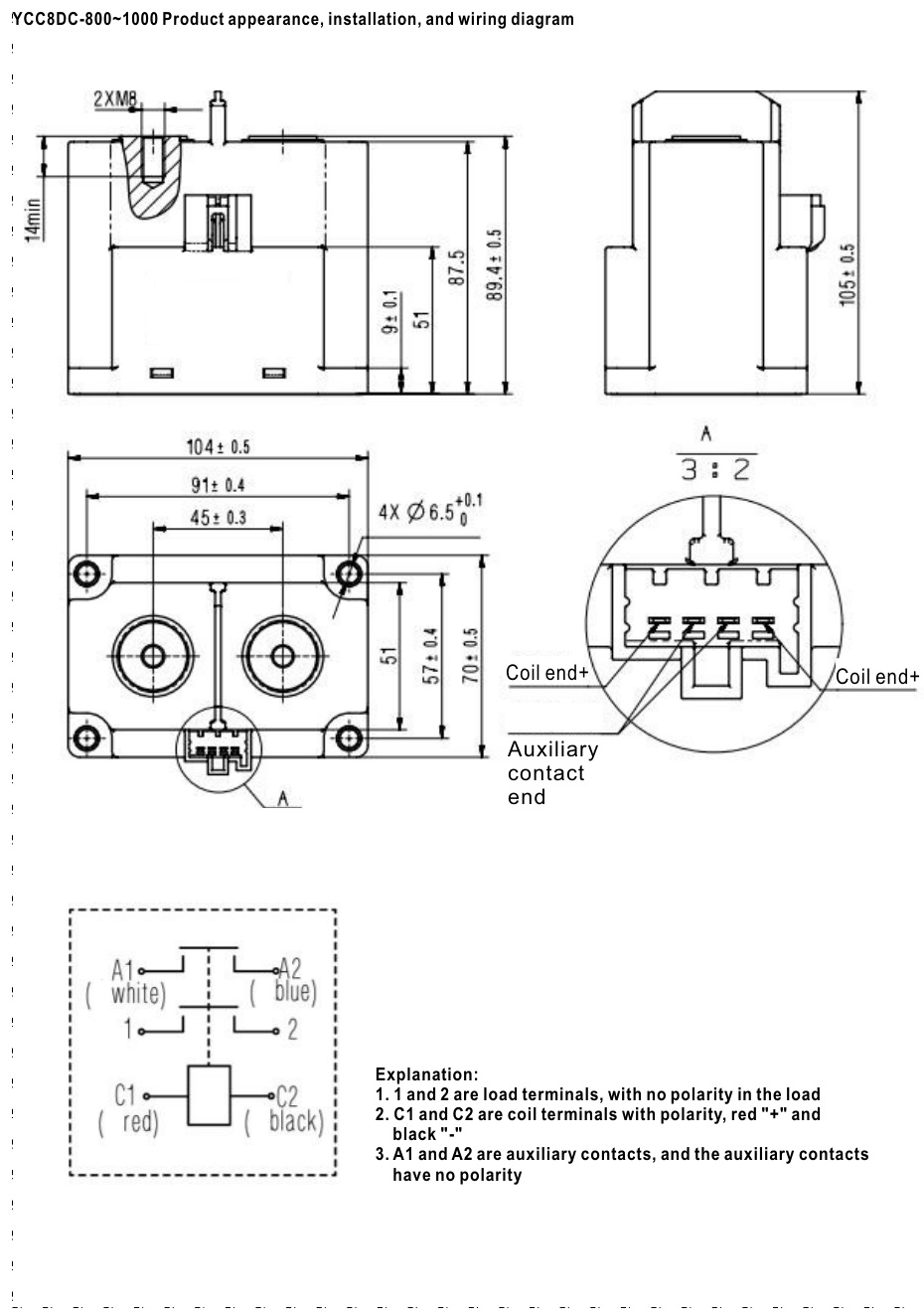
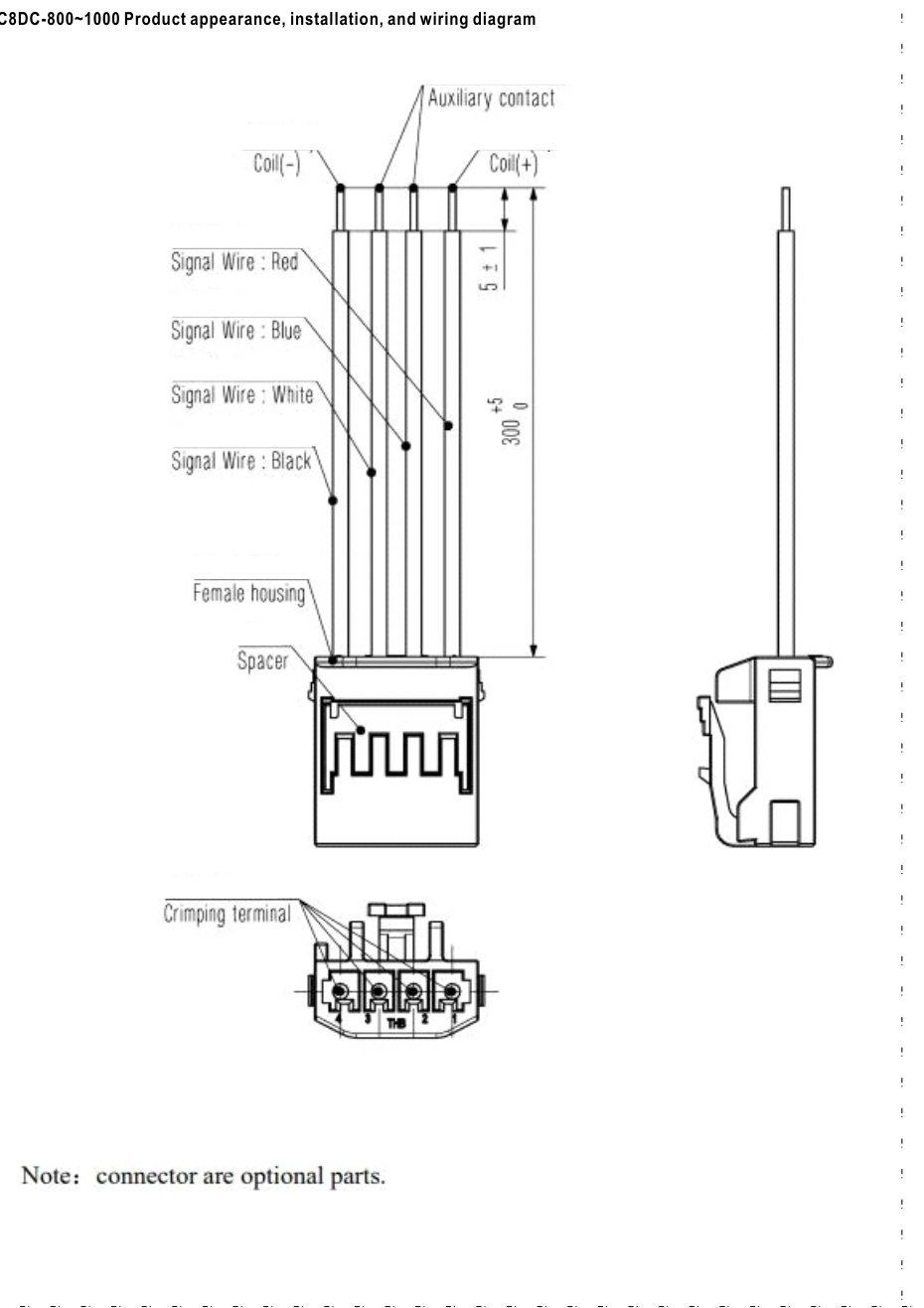
For the 40A version, follow the original non-polarized coil/load connection drawing. On the larger versions the main terminals 1/2 are non-polarized, but coil leads C1/C2 are polarized: red positive and black negative. Auxiliary leads A1/A2 are non-polarized. Coil resistances carry the catalogue tolerance of ±7%. The drawings below identify the applicable current-frame groups; use the drawing for the selected frame. The original photographs show the selected 40A and 400A versions. The contactor does not replace coordinated overcurrent protection.
Typical applications
Battery energy-storage switching; photovoltaic and high-voltage DC distribution; DC load isolation and control.
Original technical data and drawings
The following manufacturer figures retain the original technical content. Dimensions are in millimetres unless otherwise marked. Refer to the model and frame labels when using a shared family drawing.