



NewTrend · Machine-tool control transformers
Product overview
General application
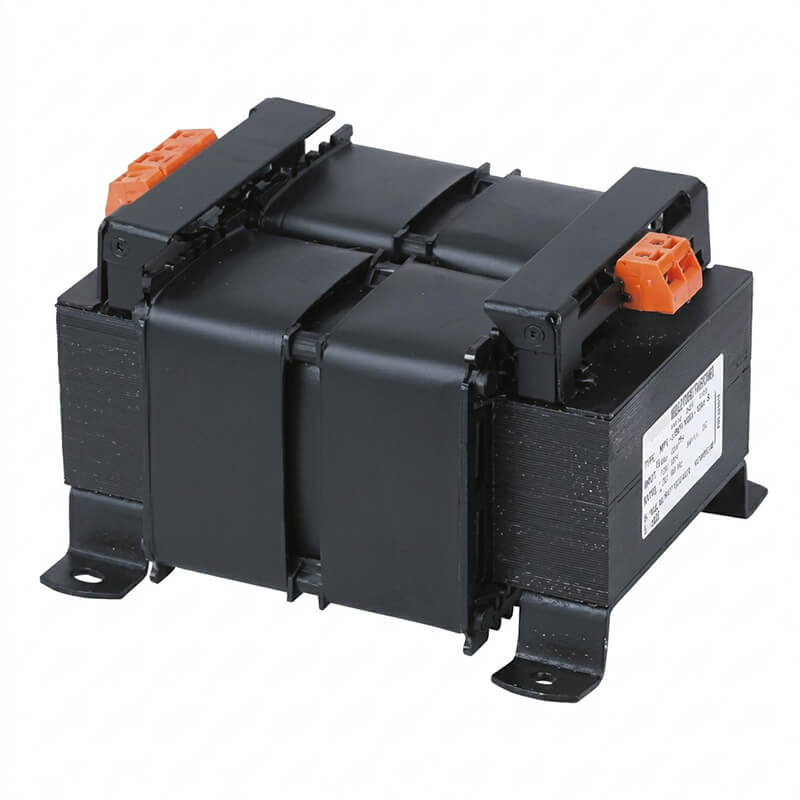
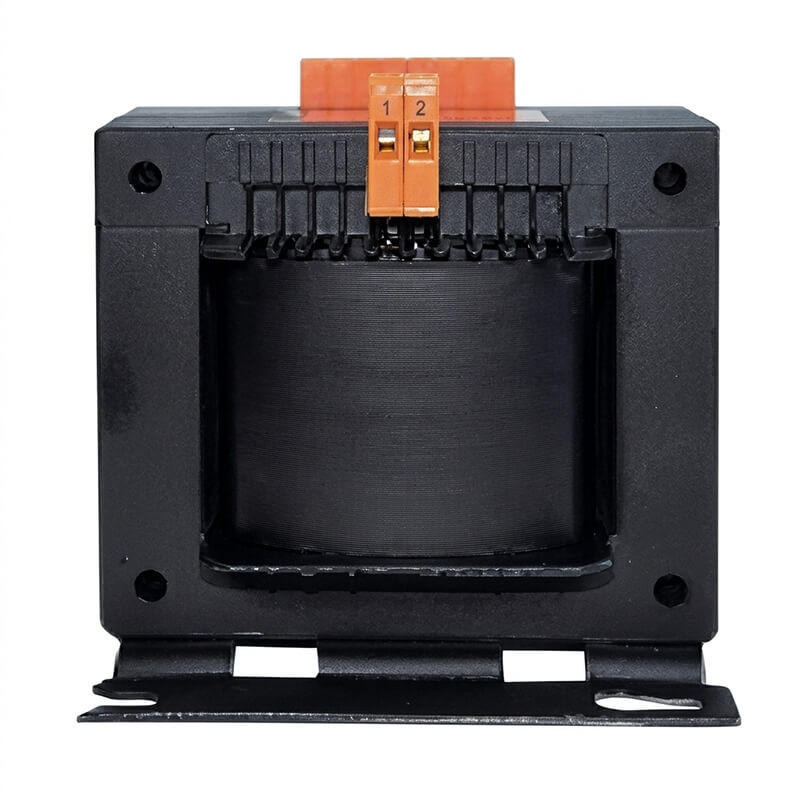
JBK3 and JBK5 transformers supply control circuits, local lighting and indicator lamps on machine tools and other industrial equipment. They are intended for 50–60 Hz AC circuits up to 660 V. The published standard primary configurations are listed in the voltage table.
Construction and wiring
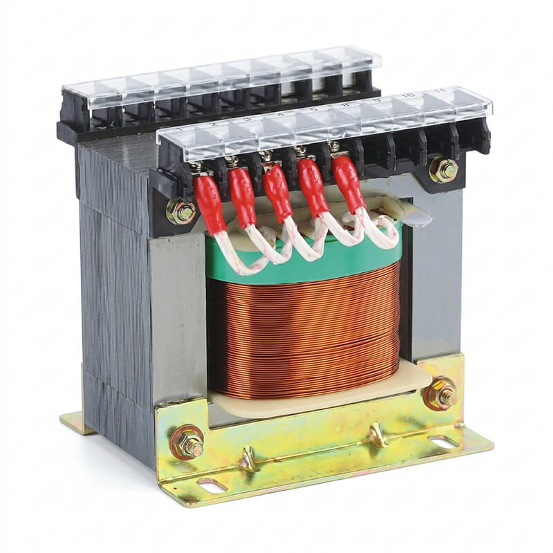
The compact construction is designed for low energy loss and accessible terminal wiring. Separate control, lighting and indication windings let the transformer supply multiple loads. The available apparent power of each winding depends on the winding allocation.
Model designation
JBK3 series
JBK3–[VA]
- J
- Machine tool
- B
- Transformer
- K
- Control
- 3
- Design number
- VA
- Rated apparent power
JBK5 series
JBK5–[VA]
- J
- Machine tool
- B
- Transformer
- K
- Control
- 5
- Design number
- VA
- Rated apparent power
The design number identifies the series. The suffix gives the rated capacity in VA. Confirm the voltage pairing and winding allocation for the selected design and capacity.
Primary and secondary voltages
Primary configurations listed by the manufacturer are 380 V, 220 V or 380(220) V. The secondary voltage notation below follows the published table.
| Specifications | Primary voltage(V) | Secondary voltage(V) | ||
|---|---|---|---|---|
| Control | Lighting | Indicator signal | ||
| 40VA | 380, 220 or 380(220) | 110(27)(220) (48) | 24(36) | 6(12) |
| 63VA | ||||
| 100VA | ||||
| 160VA | ||||
| 250VA | ||||
| 400VA | ||||
| 630VA | ||||
| 1000VA | ||||
| 1600VA | ||||
| 2000VA | ||||
| 2500VA | ||||
Winding capacity distribution
Published allocations are in VA. Blank cells follow the source table.
| Capacity (VA) | Capacity distribution of each winding(VA) | Capacity (VA) | Capacity distribution of each winding(VA) | ||||
|---|---|---|---|---|---|---|---|
| Control | Lighting | Indication | Control | Lighting | Indication | ||
| 40 | 40 | 400 | 400 | ||||
| 40 | 390 | 10 | |||||
| 37 | 3 | 320 | 80 | ||||
| 310 | 80 | 10 | |||||
| 63 | 63 | 630 | 630 | ||||
| 60 | 3 | 610 | 20 | ||||
| 20 | 40 | 3 | 510 | 120 | |||
| 60 | 3 | 490 | 120 | 20 | |||
| 100 | 100 | 100 | 1000 | ||||
| 100 | 980 | 20 | |||||
| 90 | 10 | 880 | 120 | ||||
| 90 | 10 | 860 | 120 | 20 | |||
| 40 | 60 | ||||||
| 50 | 40 | 10 | |||||
| 160 | 160 | 1600 | 1600 | ||||
| 90 | 60 | 10 | 1580 | 20 | |||
| 100 | 60 | 1400 | 200 | ||||
| 150 | 10 | 1380 | 200 | 20 | |||
| 250 | 250 | 2000 | 2000 | ||||
| 240 | 10 | 1980 | 20 | ||||
| 170 | 80 | 1800 | 200 | ||||
| 160 | 80 | 10 | 1780 | 200 | 20 | ||
The original right-hand capacity cell above the 1000 VA allocation reads 100. The allocation values are reproduced as published and should be confirmed before selection.
Outline and mounting dimensions
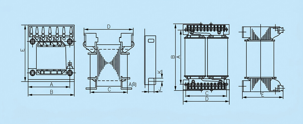
| Rated capacity(VA) | Outline size(mm) | Mounting hole J×K(mm) | ||||
|---|---|---|---|---|---|---|
| B max | D max | E max | A | C | ||
| 40 | 79 | 73 | 92 | 66 | 47 | 5×9 |
| 63 | 79 | 73 | 92 | 66 | 47 | 5×9 |
| 100 | 85 | 89 | 97 | 72 | 64 | 5×9 |
| 160 | 97 | 91 | 105 | 84 | 73.5 | 7×14 |
| 250 | 97 | 105 | 105 | 84 | 85 | 7×14 |
| 400 | 121 | 103 | 122 | 100 | 85 | 6×10 |
| 630 | 151 | 111 | 143 | 133 | 90 | 6×10 |
| 1000 | 215 | 170 | 150 | 142 | 160 | 8×14 |
| 1600 | 245 | 185 | 155 | 155 | 180 | 8×14 |
| 2000 | 275 | 210 | 175 | 175 | 210 | 8×14 |
The source gives mounting dimensions through 2000 VA. Confirm the mounting dimensions for 2500 VA.
Typical applications
- Machine tool and machinery control circuits.
- Local machine lighting at 24 V or 36 V.
- Indicator and signal circuits at 6 V or 12 V.
Custom winding configurations
Alternative winding allocations are available for applications that need different control, lighting or indication loads.