

NewTrend · modular-contactor auxiliary contacts
Product overview
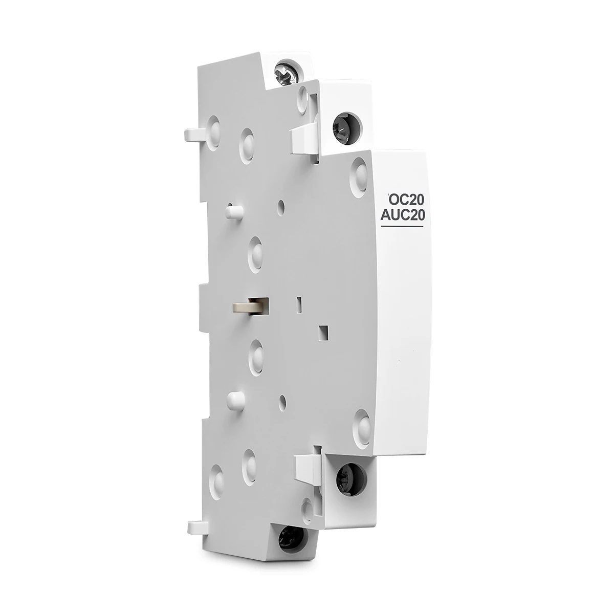
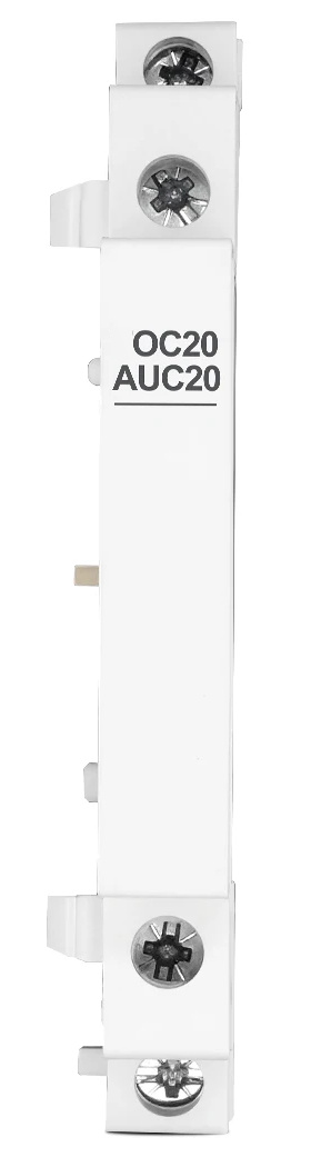
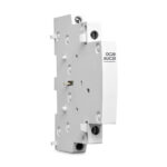
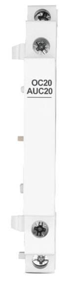
The OC20 / AUC20 is a slim auxiliary contact module for compatible household modular contactors. Its two normally open contacts follow the contactor mechanism to provide contact-state feedback and control-circuit signals. The 9mm format fits alongside the host contactor in a distribution-board assembly.
Technical selection summary
| Model references | OC20 / AUC20 |
|---|---|
| Product type | Mechanically coupled auxiliary contact module |
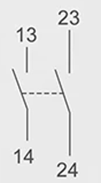
| Contact arrangement | 2NO |
| Terminals | 13–14 and 23–24 |
| AC-12 rating | 240V AC; resistive load below 5A |
| AC-15 rating | 230V AC; load below 2A |
| DC-13 rating | 130V DC; inductive load below 1A |
| Insulation voltage Ui | 500V AC |
| Rated AC frequency | 50/60Hz |
| Protection | IP20 |
| Standard marking | IEC60947-5-1 |
| Module width | 9mm |
| Front height | 81mm |
| Outline references | 66mm depth; 45mm front section; 35mm mounting reference |
| Installation | Side coupling to a compatible modular contactor; 35mm DIN-rail assembly |
| Ambient temperature | −5°C to +40°C; 24-hour average not above +35°C |
| Altitude | Below 2000m |
| Pollution degree | 2 |
Two normally open auxiliary contacts
The illustrated module uses two mechanically linked normally open contact pairs: terminals 13–14 and 23–24. They change state with the host contactor mechanism, allowing its operating state to be used in a monitoring or interlocking control circuit.
Control-circuit ratings
For AC-12 use, the supplied parameters specify 240V AC with resistive load below 5A. For AC-15 use, they specify 230V AC with load below 2A. For DC-13 use, the stated limit is 130V DC with inductive load below 1A. Insulation voltage Ui is 500V AC, and the module carries the IEC60947-5-1 marking.
Side coupling and installation
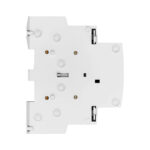
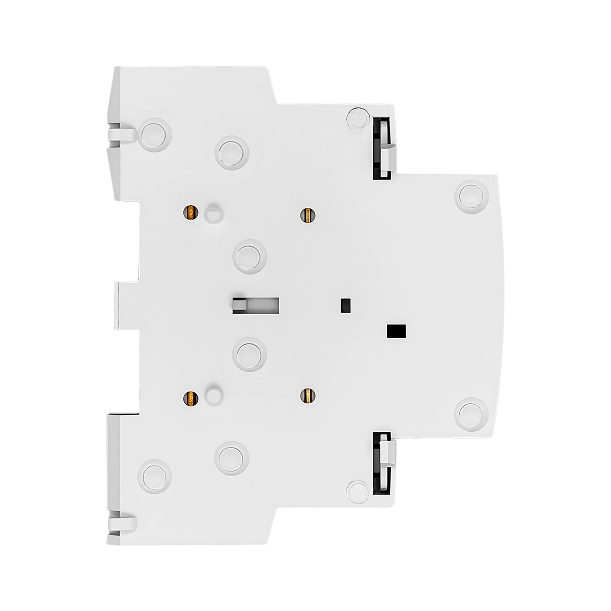
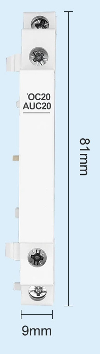
Align the auxiliary module with the compatible host contactor. Engage the lower coupling first, then close and secure the upper connection. Check that the mechanical linkage and clips are fully engaged before wiring. The mounting features below show the coupling side of the module.
Install the complete assembly vertically on a standard 35mm DIN rail. Isolate the circuit before installation, tighten the terminal screws securely and ensure that the contact arrangement and electrical ratings match the control circuit.
Dimensions
The front is 81mm high and 9mm wide. The supplied outline also gives a 66mm depth, 45mm front-section reference and 35mm mounting reference. Allow room beside the contactor for the auxiliary module and its wiring.
Operating environment
Use within −5°C to +40°C, with the 24-hour average no higher than +35°C, at an altitude below 2000m. Relative humidity is limited to 50% at +40°C and 90% at +25°C. Use a pollution-degree-2 installation location without severe impact, vibration or excessive external magnetic fields.
Typical applications
For modular-contactor state indication, building-automation feedback, control-circuit interlocks and remote monitoring of lighting, heating and other contactor-controlled loads.