


NewTrend · three-phase MODBUS energy metering
Product overview
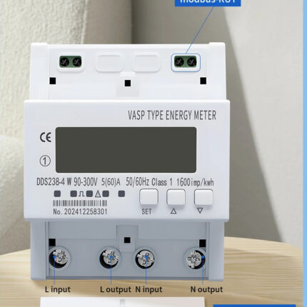
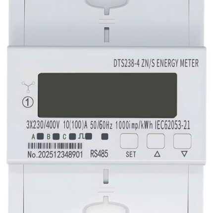
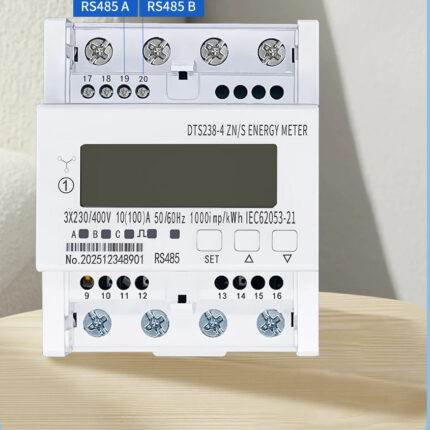
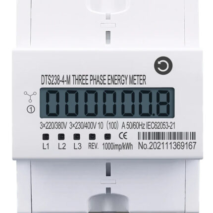
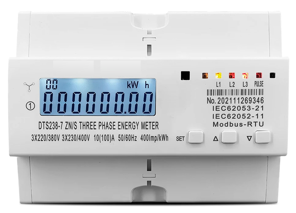
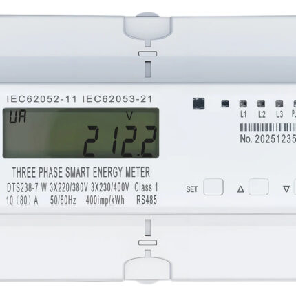
The DTS238-7 ZN/S combines three-phase electrical-parameter monitoring, bidirectional energy measurement and RS485 communication. This direct-connected 10(100)A version is marked for 3 × 220/380V and 3 × 230/400V at 50/60Hz. The backlit LCD and front keys provide local readings, while MODBUS-RTU supports remote data collection.
Technical selection summary
| Model | DTS238-7 ZN/S |
|---|---|
| System | Three-phase four-wire AC |
| Nameplate voltage ratings | 3 × 220/380V and 3 × 230/400V |
| Rated / maximum current | 10(100)A; direct connection |
| Frequency | 50/60Hz |
| Accuracy | Active energy Class 1; RMS Class 0.5 |
| Limit voltage range | 70–120% Un |
| Measurements | Phase voltage/current, phase and total active/reactive power, power factor and frequency |
| Energy registers | Total, import and export active energy; total reactive energy |
| Display | Backlit LCD; SET, up and down keys |
| Phase indication | L1, L2 and L3; phase-loss indication |
| Pulse constant | 400imp/kWh on the illustrated unit |
| Pulse output | Passive, optically isolated; 80 ±5ms |
| RS485 | MODBUS-RTU; 1200–9600bps; default 9600bps |
| Serial format | 8 data bits, no parity, 1 stop bit; address 1–247 |
| Data retention | More than 15 years without power |
| Protection | IP20 |
| Mounting | 35mm DIN rail |
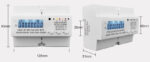
| Enclosure drawing | 93mm height × 126mm width; 51mm depth reference; 45mm front section |
| Standard markings | IEC62053-21; IEC62052-11 |
Bidirectional energy and phase readings
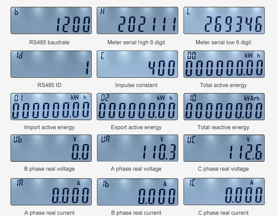
The meter displays total, imported and exported active energy, plus total reactive energy. Reverse active energy is included in the total accumulation. Individual phase voltages and currents, phase and total active/reactive power, phase and total power factor, and frequency can be viewed from the front keys. Communication address, baud rate, pulse constant and the meter serial-number sections are also displayed.
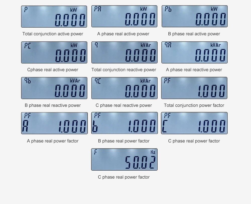
Power and power-factor display
The display sequence distinguishes total readings from A, B and C phase readings. The screens below show active power, reactive power, power factor and frequency. The illustrated meter carries a 400imp/kWh pulse constant, with separate phase and energy-pulse indicators on the front panel.
Three-phase wiring and auxiliary terminals
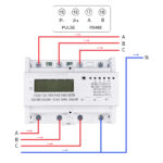
The connection diagram identifies A, B and C phase paths and neutral. Lower terminals are the phase inputs; the upper phase terminals are the outputs. Follow the meter’s molded terminal markings and isolate the supply before wiring.
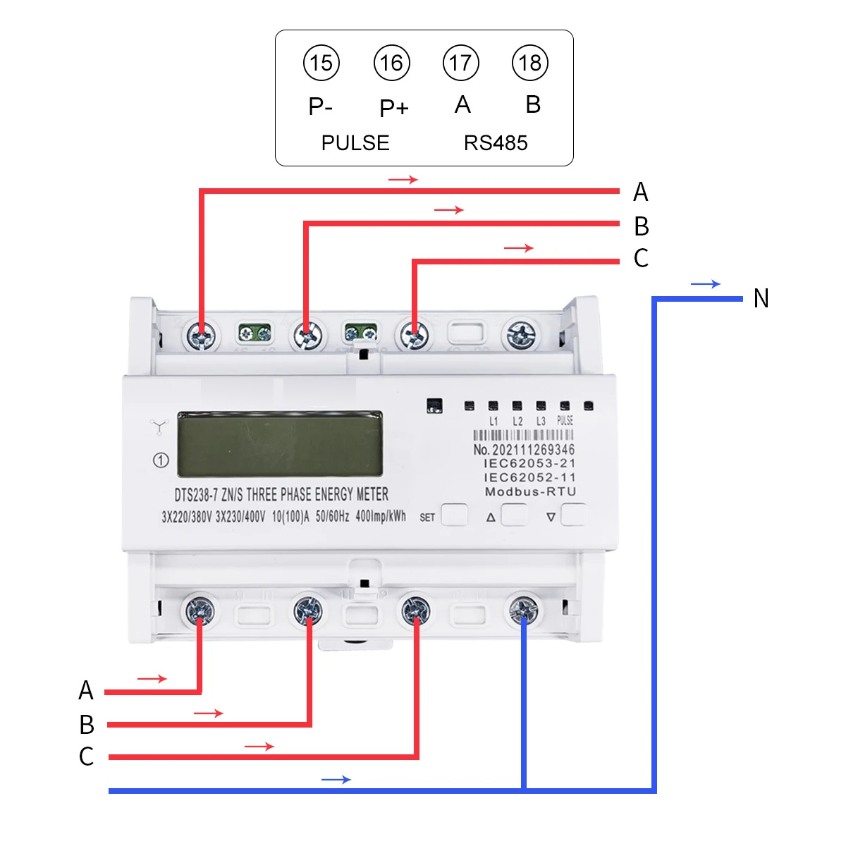
| Terminal 15 | Pulse P− |
|---|---|
| Terminal 16 | Pulse P+ |
| Terminal 17 | RS485 A |
| Terminal 18 | RS485 B |
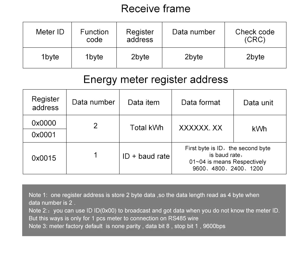
RS485 energy registers
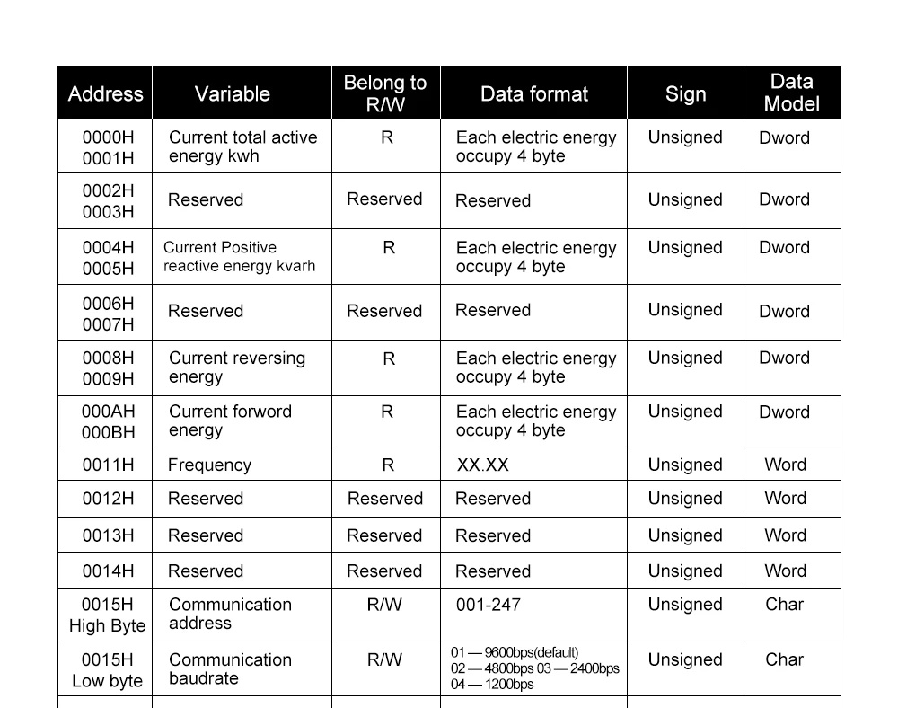
MODBUS-RTU uses selectable baud rates from 1200 to 9600bps, default 9600bps, with no parity. The communication address is configurable from 1 to 247. The energy-register table below lists addresses, read/write access, scaling and data formats. Use the specified register pairs and word order when integrating a data collector.
Electrical-parameter registers
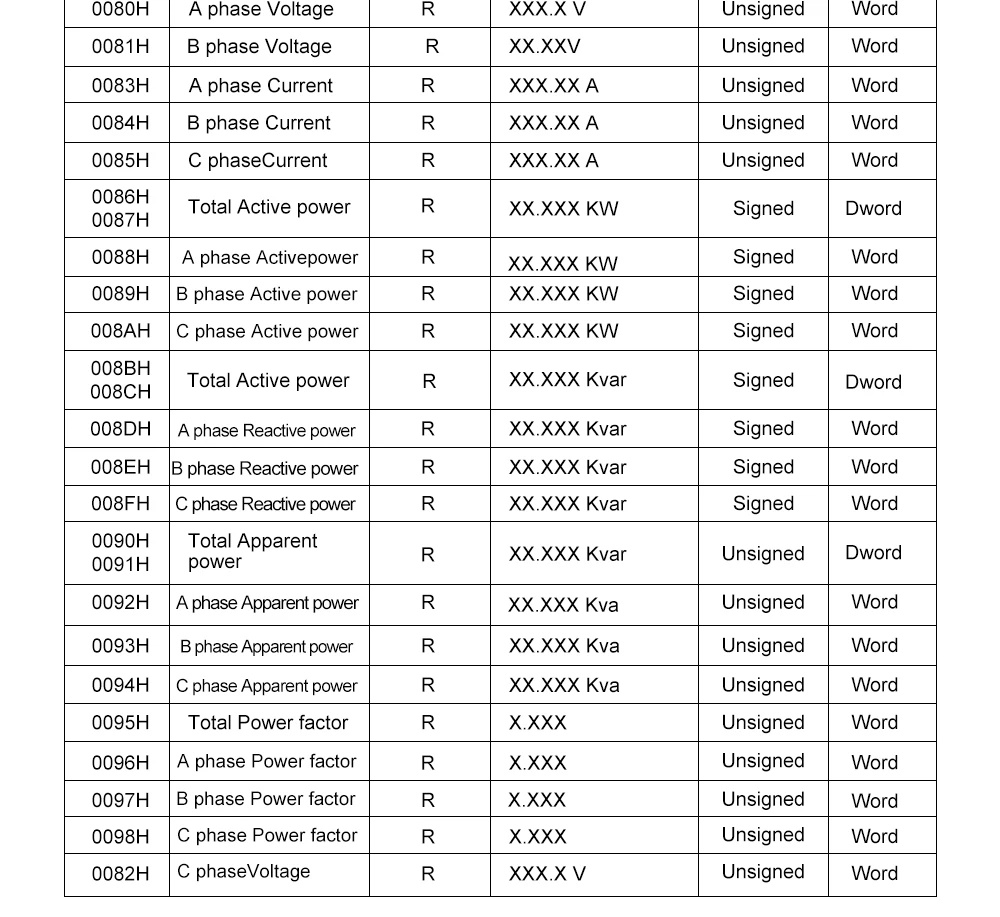
The additional register table covers individual phase voltage and current, phase and total power, and power-factor values. Keep the indicated signed or unsigned format and decimal scaling for each variable.
MODBUS command and response frames
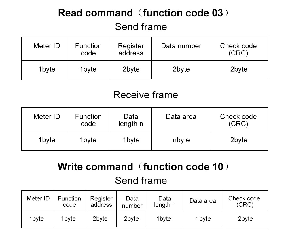
The protocol diagrams describe function 03 read commands and function 10 write commands, with meter address, start register, register count, data bytes and CRC fields. The response examples also identify energy-register addresses and the communication configuration register. Apply write commands only to the supported writable settings.
Dimensions and mounting
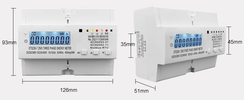
The supplied drawing shows a 93mm height, 126mm width, 51mm depth reference, 35mm rail section and 45mm front section. Mount the enclosure on a 35mm DIN rail in a suitable distribution board, keeping the terminals and front keys accessible.
Typical applications
For three-phase residential and commercial submetering, industrial distribution monitoring, bidirectional energy recording and RS485 data-collection systems.