


CNC Electric · SUL181h
Product overview
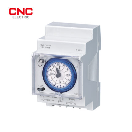
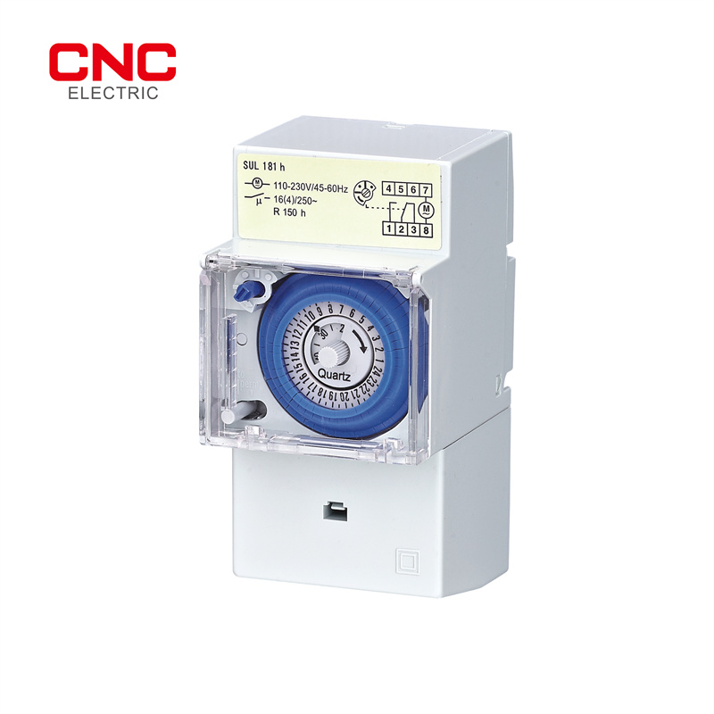
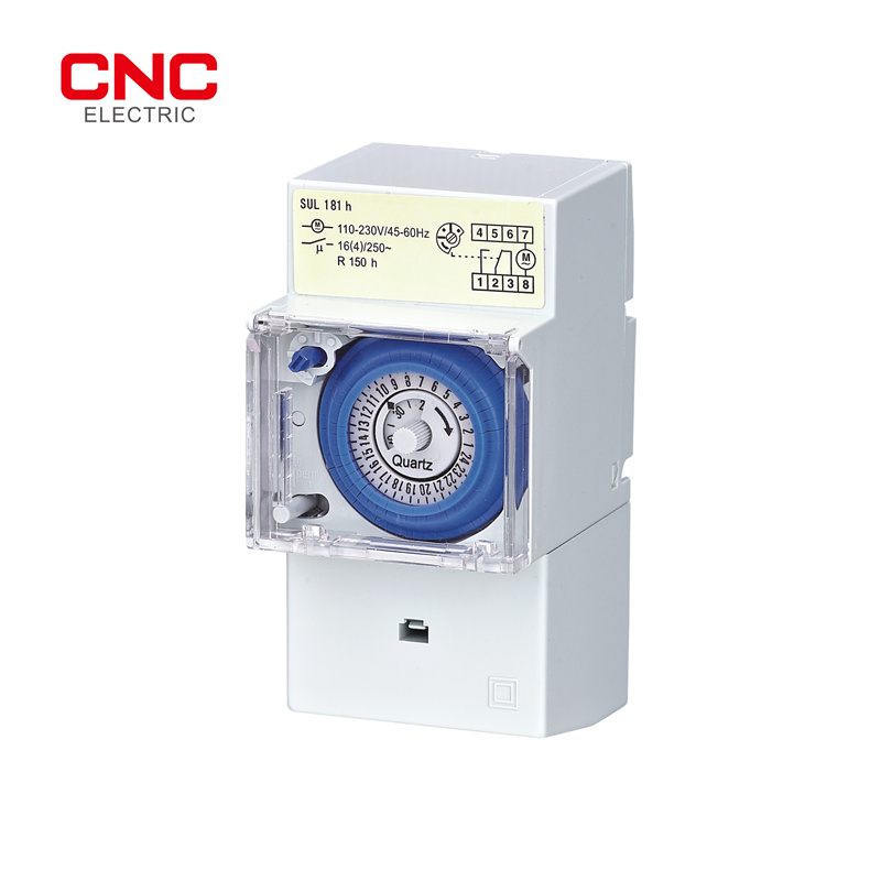
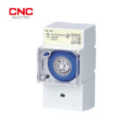
The CNC Electric SUL181h is a quartz-controlled analogue daily time switch with 48 switching segments and a 30-minute minimum setting interval. This original photographed version is marked 110–230V AC and R150h, with a 16(4)A contact marking at 250V AC.
Technical selection summary
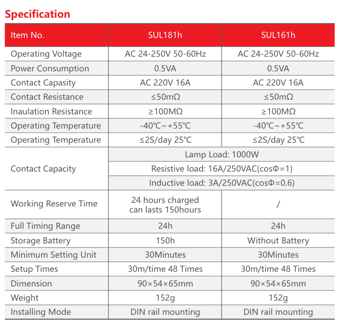
| Manufacturer model | SUL181h |
|---|---|
| Supply on the original unit | 110–230V AC, 45–60Hz |
| Shared catalogue supply range | AC24–250V, 50–60Hz; the photographed 110–230V marking governs this listing |
| Program / segments | 24-hour daily program / 48 segments |
| Minimum setting interval | 30 minutes |
| Contact marking | 16(4)A at 250V AC, original unit |
| Resistive duty | 16A at 250V AC, cosφ = 1 |
| Inductive duty in the catalogue | 3A at 250V AC, cosφ = 0.6; retained separately from the 16(4)A marking |
| Lamp load | 1,000W |
| Reserve | R150h on the unit; original catalogue specifies 150 hours after 24 hours charging |
| Clock accuracy | ≤2 seconds/day at 25°C |
| Power consumption | 0.5VA |
| Operating ambient | −40°C to +55°C, original catalogue |
| Dimensions / mounting | 90 × 54 × 65mm / DIN rail |
| Switching / wiring | One changeover output; follow the original numbered-terminal diagram |
Selection and installation
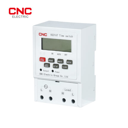
This is the original CNC R150h and 110–230V-labelled version, separate from the NewTrend AC230V R3d unit. The original catalogue gives a wider supply range and a 3A inductive duty; its conditions and the unit markings are shown separately. The catalogue dimension table states 90 × 54 × 65mm, but its shared drawing shows a different 110mm width and is not adopted for this version. Confirm the supplied unit envelope before panel fabrication. Follow the numbered terminal diagram on the actual unit. The separately linked 220V/R3d instructions describe a different version and are not applied to this R150h listing. Timekeeping reserve does not power the load. Use a contactor above the applicable switching duty.
Typical applications
Daily lighting, signs, ventilation and compatible load-control circuits requiring a mechanical dial and short-term clock reserve.
Original technical data and drawings
The following manufacturer figures retain the original technical content. Dimensions are in millimetres unless otherwise marked. Refer to the model and frame labels when using a shared family drawing.