



NewTrend · PV DC Miniature Circuit Breaker
Product overview
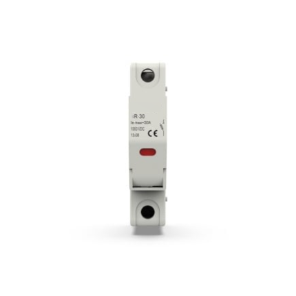
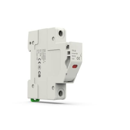
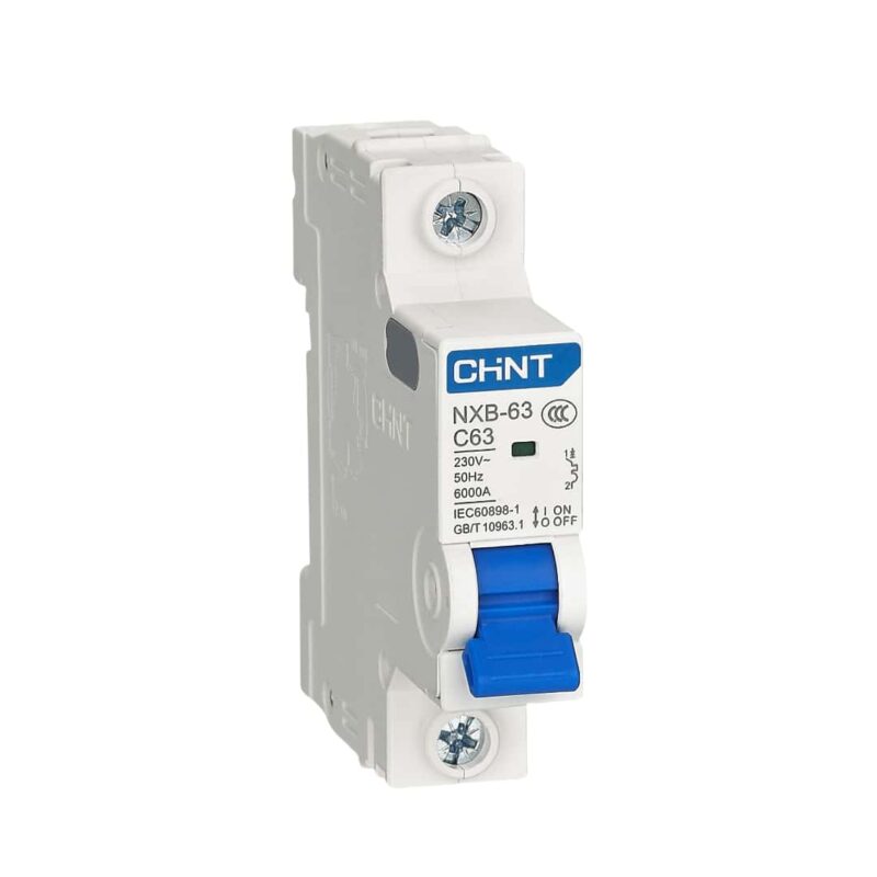
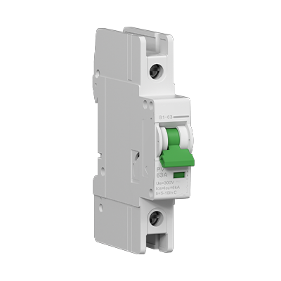
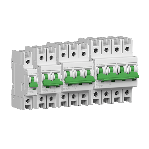
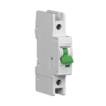
B1-63 is a non-polarized thermal-magnetic DC miniature circuit breaker for overcurrent protection in photovoltaic, battery storage and UPS circuits. This listing is the 1P, 63A, 300V DC, C-curve configuration. Arc-flash barriers and the extended housing support electrical clearance and creepage distance.
Key features
- 1P, 63A, 300V DC; 6kA Icu and Ics.
- Non-polarized construction with thermal-magnetic tripping.
- Arc-flash barriers and extended housing.
- 35mm DIN-rail mounting; optional auxiliary contacts and shunt releases.
Technical selection summary
Selected product configuration
| Model | B1-63 |
|---|---|
| Configuration on this page | 1P, 63A, 300V DC, C curve |
| Poles | 1P |
| Rated current In | 63A |
| Rated working voltage Ue | 300V DC |
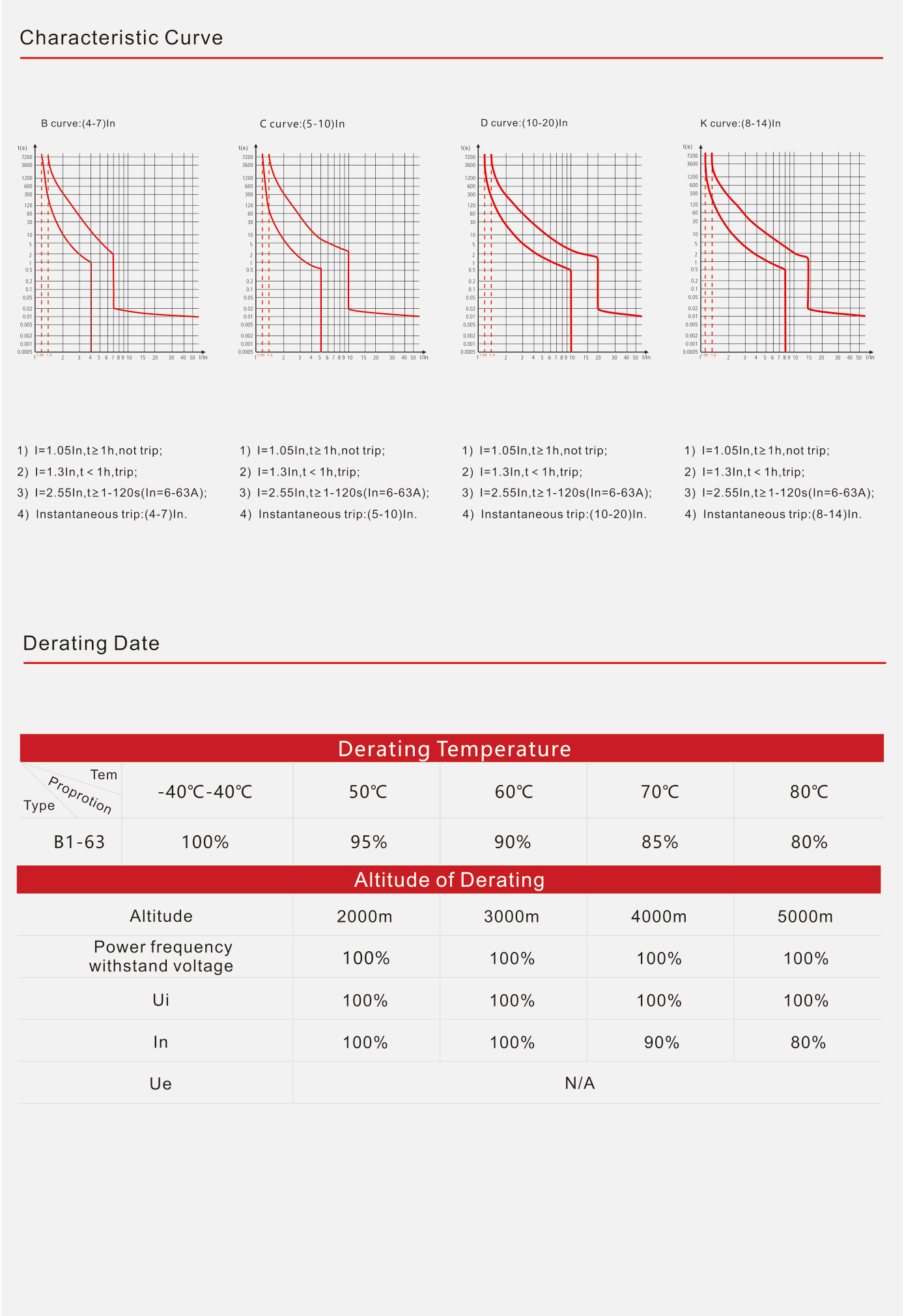
| Tripping curve | C; instantaneous 5–10 × In |
| Trip mechanism | Thermal magnetic |
| Polarity | Non-polarized |
| Ultimate breaking capacity Icu | 6kA |
| Service breaking capacity Ics | 6kA |
| Rated insulation voltage Ui | 1200V DC |
| Rated impulse withstand voltage Uimp | 6kV |
| Standards | IEC 60947-2 / GB/T 14048.2 |
Mechanical and electrical endurance
| Mechanical operations, actual / standard value | 10000 / 9700 cycles |
|---|---|
| Electrical operations, actual / standard value | 1000 / 300 cycles |
Installation and environment
| Ingress protection, body / terminals | IP40 / IP20 |
|---|---|
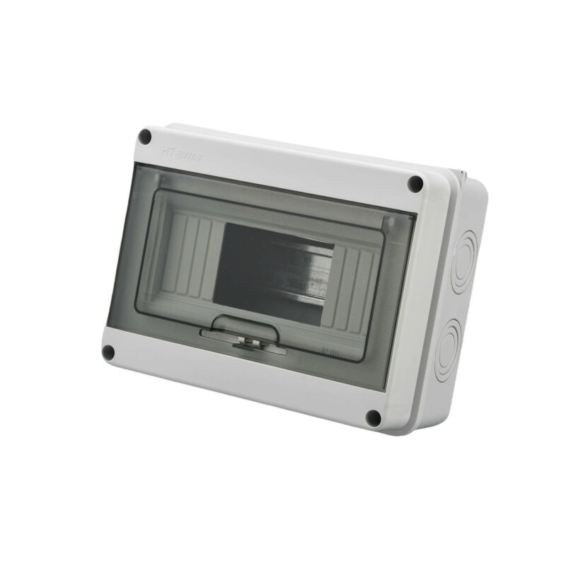
| Optional enclosure | IP65 polycarbonate enclosure; not included in the listed bare-breaker configuration |
| Terminal conductor cross-section | 2.5–25mm² |
| M5 terminal tightening torque | 2–2.5N·m |
| Operating temperature | −40°C to +80°C |
| Storage temperature | −40°C to +85°C |
| Humidity and heat resistance | Class II; 55°C and 95% relative humidity |
| Mounting | 35mm DIN rail |
Family reference ratings
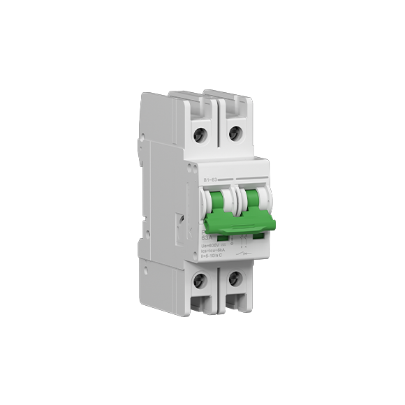
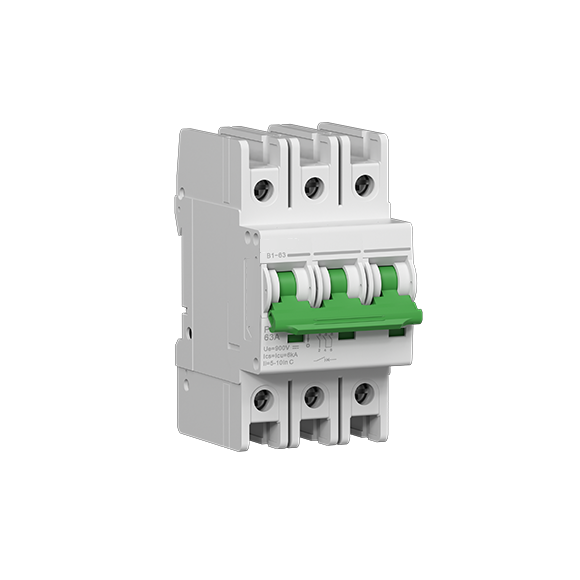
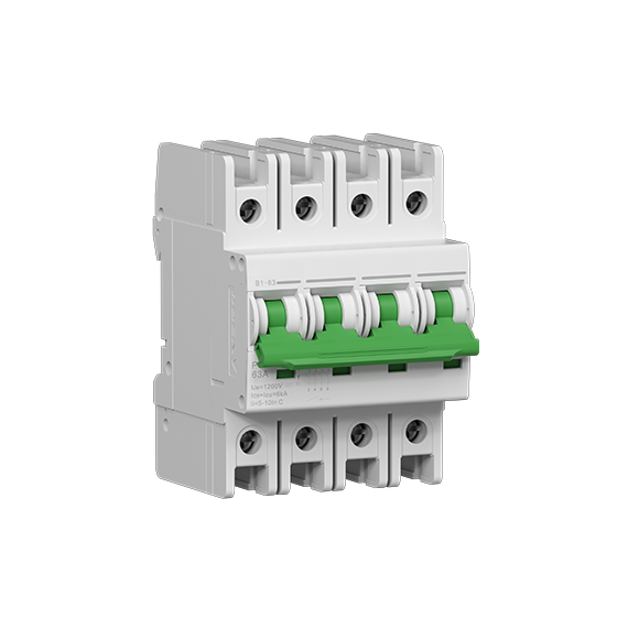
| Pole-to-voltage correspondence | 1P: 300V DC; 2P: 600V DC; 3P: 900V DC; 4P: 1200V DC |
|---|---|
| Family maximum rated current Ith | 63A |
| Family rated currents | 6A, 10A, 13A, 16A, 20A, 25A, 32A, 40A, 50A, 63A |
| Reference curve instantaneous ranges | B: 4–7 × In; C: 5–10 × In; D: 10–20 × In; K: 8–14 × In |
| Thermal reference points | 1.05 × In: ≥1h, no trip; 1.3 × In: <1h, trip; 2.55 × In: 1–120s for In 6–63A |
Temperature and altitude derating
| Rated-current factor at −40°C to +40°C | 100% |
|---|---|
| Rated-current factor at +50 / +60 / +70 / +80°C | 95% / 90% / 85% / 80% |
| Altitude reference levels | 2000 / 3000 / 4000 / 5000m |
| Power-frequency withstand voltage factor | 100% at all four reference altitudes |
| Ui factor | 100% at all four reference altitudes |
| In factor at 2000 / 3000 / 4000 / 5000m | 100% / 100% / 90% / 80% |
| Ue altitude factor | N/A in the source table |
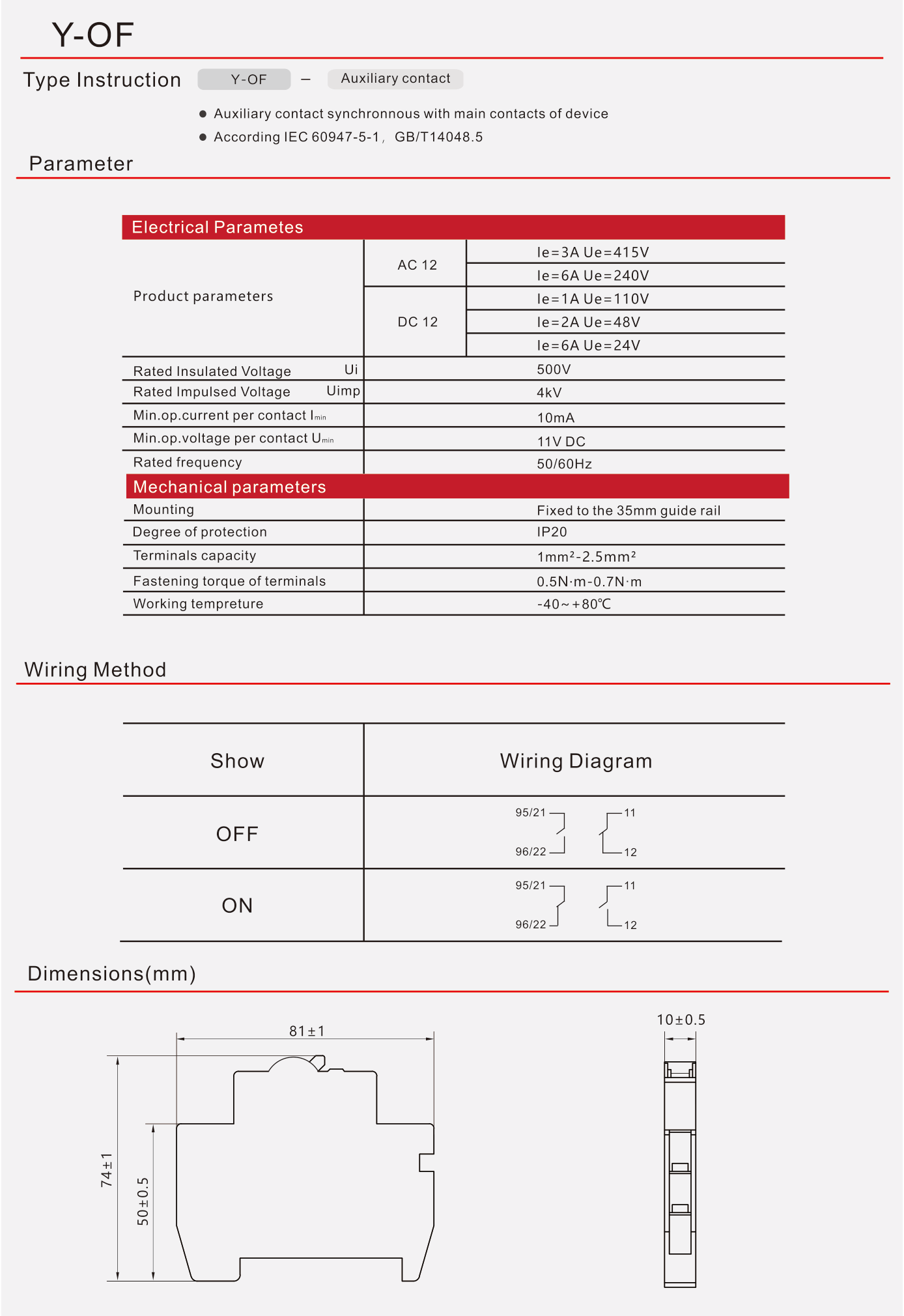
Accessory reference: Y-OF auxiliary contact
| Installation | Mount to the left of the breaker or release unit; synchronous with main contacts |
|---|---|
| Contact function | Changeover (CO) |
| Standards | IEC 60947-5-1 / GB/T 14048.5 |
| AC-12 ratings | 3A at 415V AC; 6A at 240V AC |
| DC-12 ratings | 1A at 110V DC; 2A at 48V DC; 6A at 24V DC |
| Ui / Uimp | 500V / 4kV |
| Minimum current / voltage per contact | 10mA / 11V DC |
| Rated frequency | 50/60Hz |
| Mounting / protection | 35mm DIN rail / IP20 |
| Terminal capacity / torque | 1–2.5mm² / 0.5–0.7N·m |
| Operating temperature | −40°C to +80°C |
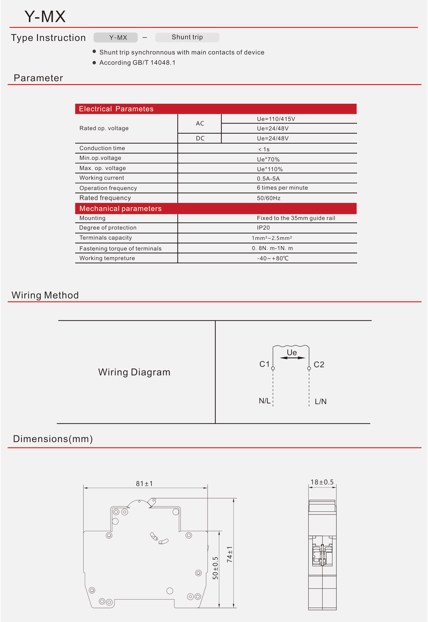
Accessory reference: Y-MX shunt release
| Standard | GB/T 14048.1 |
|---|---|
| AC operating-voltage references | 110V / 415V; 24V / 48V |
| DC operating-voltage references | 24V / 48V |
| Conduction time | <1s |
| Minimum / maximum operating voltage | 70% / 110% of Ue |
| Working current | 0.5–5A |
| Operating frequency | 6 times per minute |
| Rated frequency | 50/60Hz |
| Mounting / protection | 35mm DIN rail / IP20 |
| Terminal capacity / torque | 1–2.5mm² / 0.8–1N·m |
| Operating temperature | −40°C to +80°C |
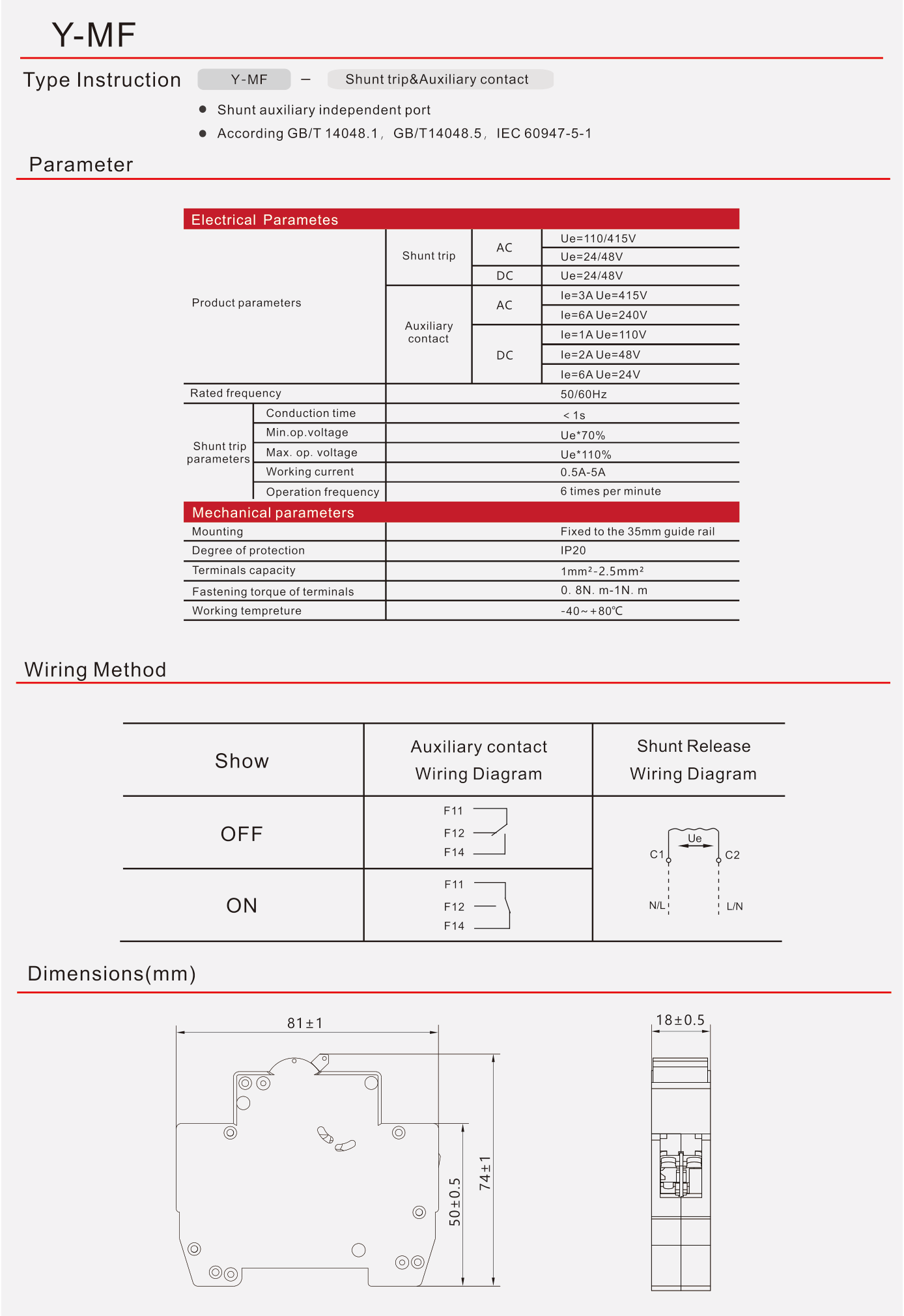
Accessory reference: Y-MF shunt release and auxiliary contact
| Wiring versions | Shared terminal and independent terminal versions; separate diagrams in PDF pages 7 and 8 |
|---|---|
| Standards | GB/T 14048.1 / GB/T 14048.5 / IEC 60947-5-1 |
| Shunt AC operating-voltage references | 110V / 415V; 24V / 48V |
| Shunt DC operating-voltage references | 24V / 48V |
| Auxiliary AC ratings | 3A at 415V AC; 6A at 240V AC |
| Auxiliary DC ratings | 1A at 110V DC; 2A at 48V DC; 6A at 24V DC |
| Rated frequency | 50/60Hz |
| Shunt conduction time | <1s |
| Shunt minimum / maximum voltage | 70% / 110% of Ue |
| Shunt current / operating frequency | 0.5–5A / 6 times per minute |
| Mounting / protection | 35mm DIN rail / IP20 |
| Terminal capacity / torque | 1–2.5mm² / 0.8–1N·m |
| Operating temperature | −40°C to +80°C |
Documentation for supplied marking
| Certification applicability | To be confirmed for the supplied product marking |
|---|
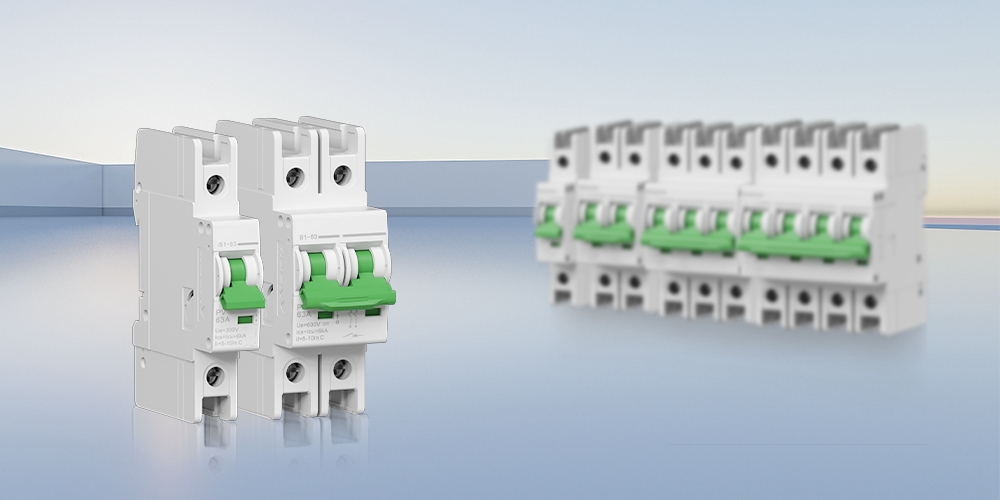
The selected configuration is 1P, 63A, 300V DC, C curve, without enclosure or accessories. The 2P–4P views, other curves and accessory drawings below are family reference material. Certification documents must match the supplied product marking.
Typical applications
- Photovoltaic DC overcurrent protection.
- Battery energy storage DC circuits within the selected configuration rating.
- UPS DC protection circuits.
Download the complete B1-63 family and accessory datasheet (8 pages)
B1-63 family reference views
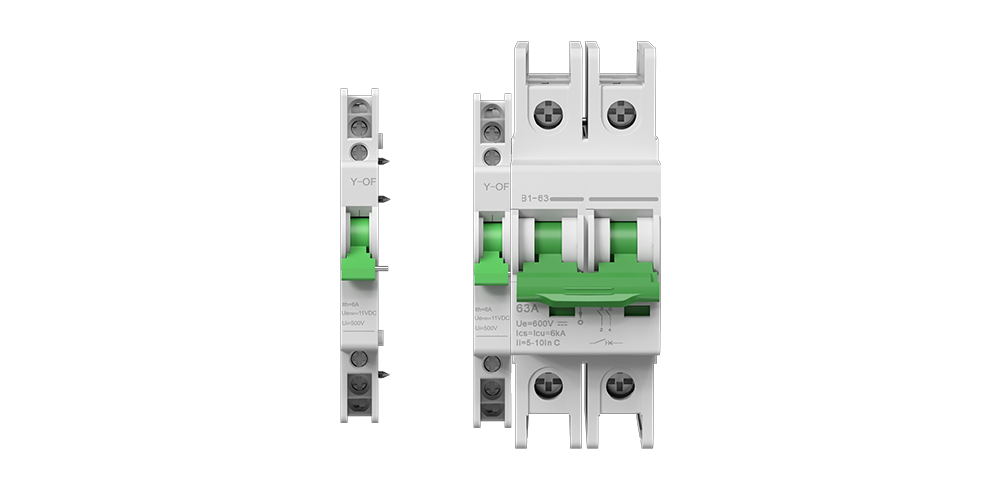
Auxiliary contact installation reference
Left-side mounting of synchronous auxiliary contacts; changeover contacts and shunt-release combinations are separate accessories.
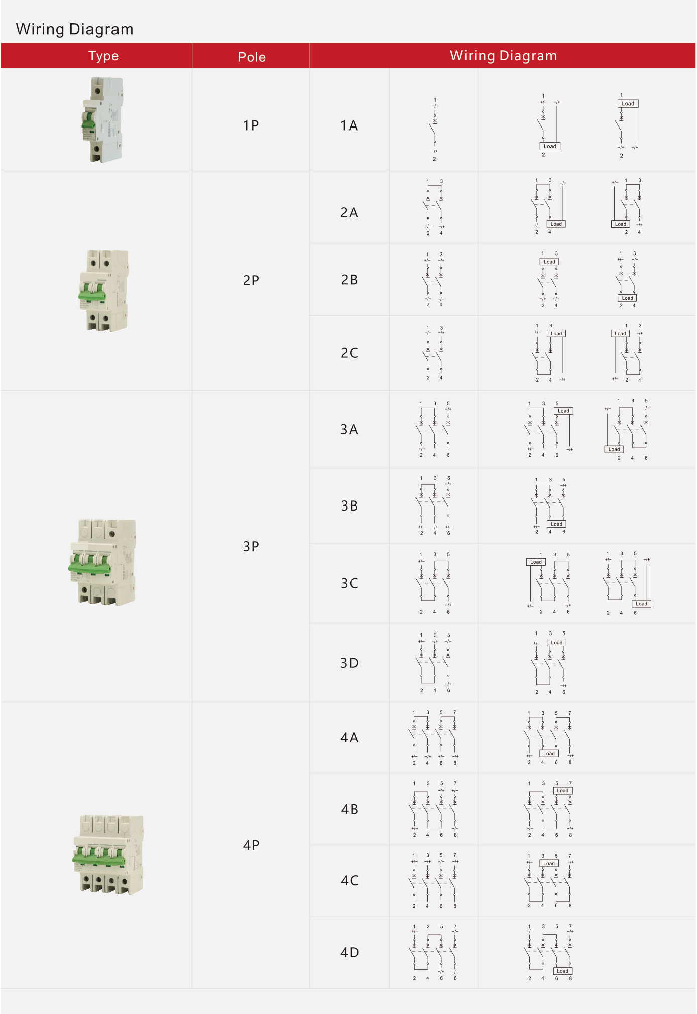
B1-63 family wiring diagrams
1P–4P series reference; use the 1P diagrams for the listed configuration.
B1-63 characteristic curves and derating
B/C/D/K family reference. The listed C curve is 5–10 × In.
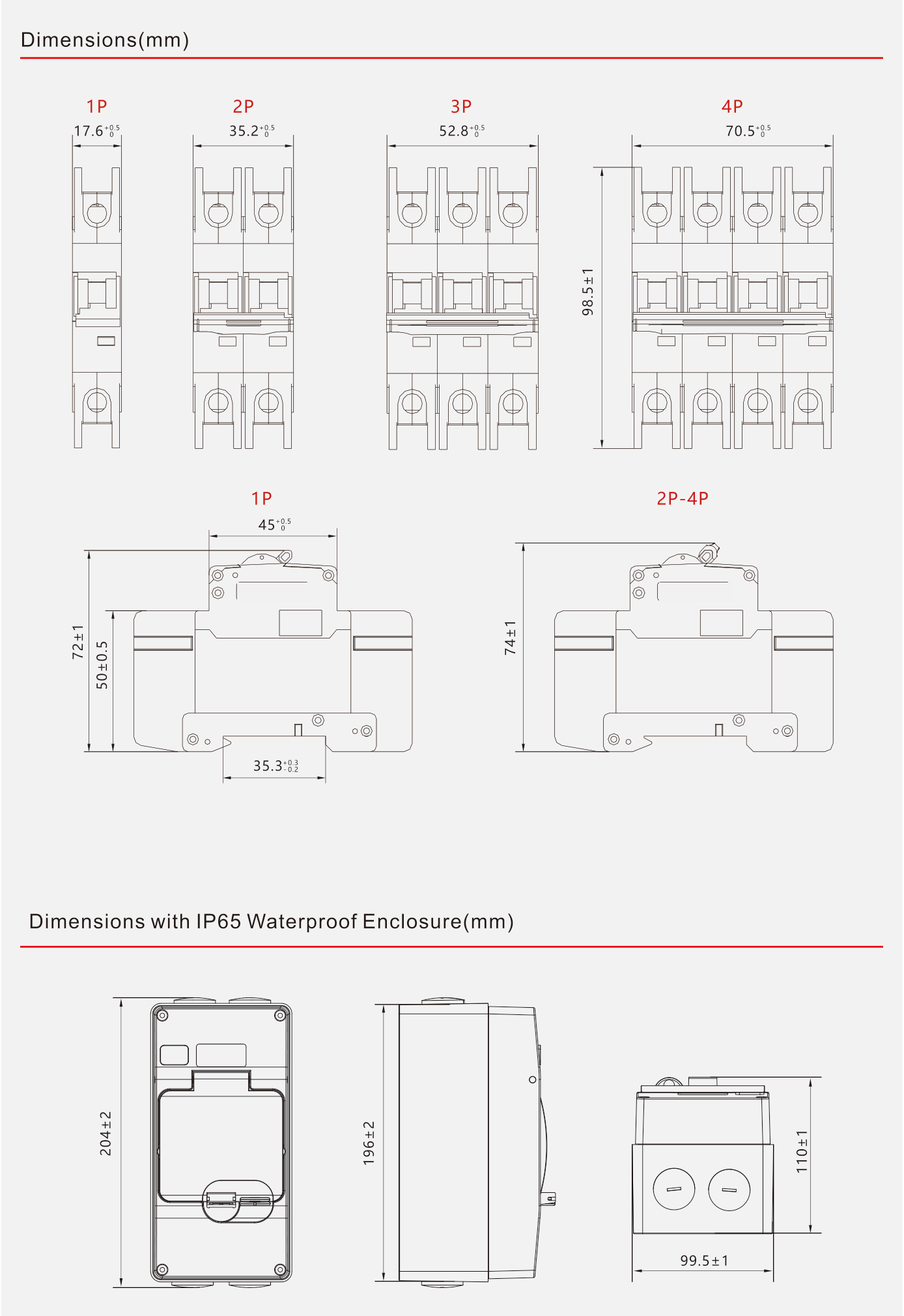
B1-63 dimensions
1P–4P family reference and optional IP65 enclosure dimensions; all dimensions in mm.
Y-OF auxiliary contact reference
Auxiliary contact parameters, wiring and dimensions; optional accessory.
Y-MX shunt release reference
Shunt release parameters, wiring and dimensions; optional accessory.
Y-MF shared-terminal reference
Shunt release and auxiliary contact with shared terminal; optional accessory.
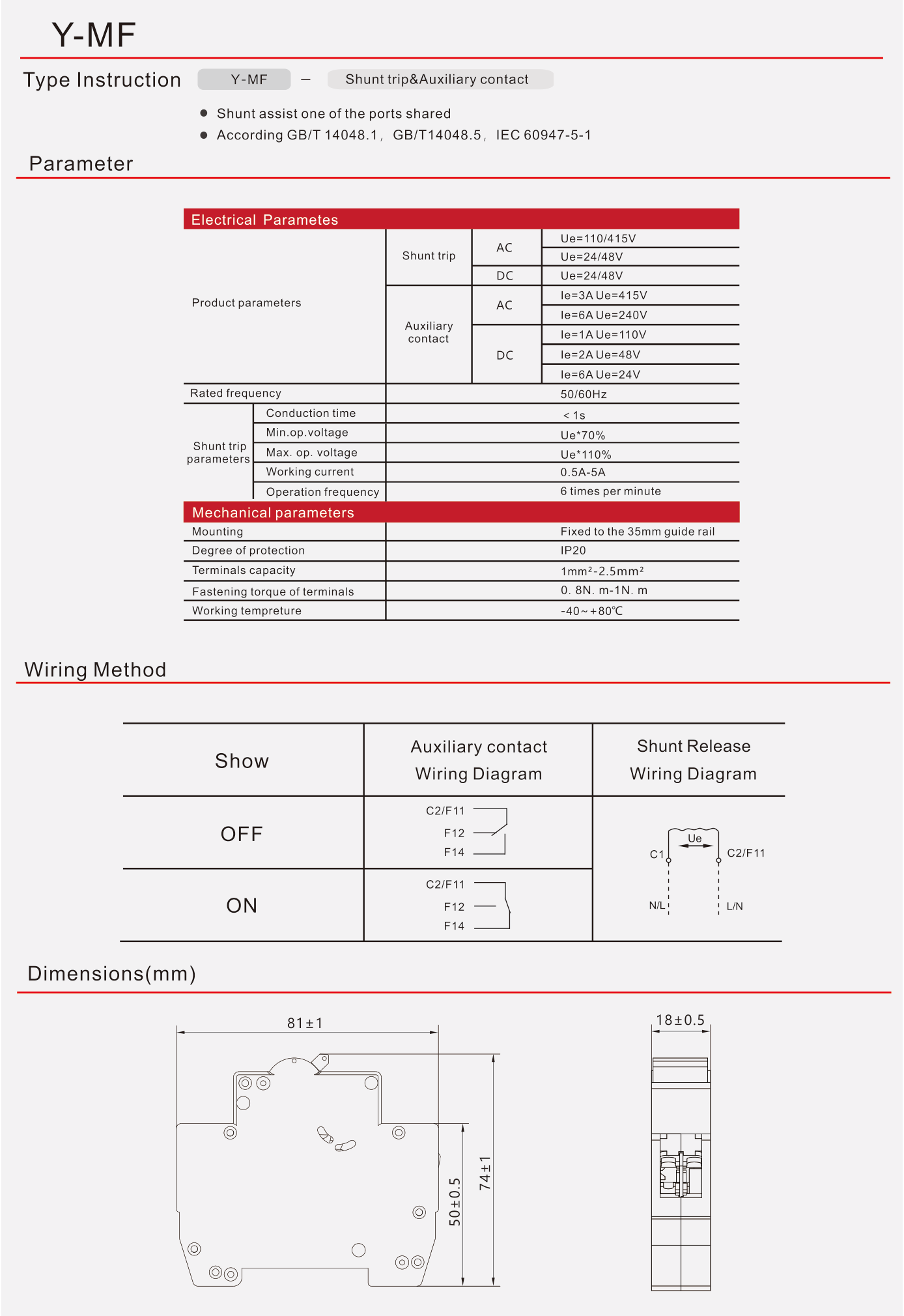
Y-MF independent-terminal reference
Shunt release and auxiliary contact with independent terminals; optional accessory.