





NewTrend · DIN-rail switching power supply
Product overview
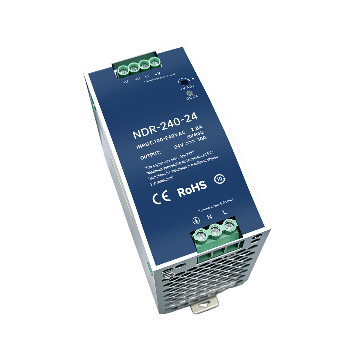
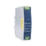
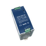
The NDR series converts AC mains to an adjustable DC output in a slim metal DIN-rail enclosure. This page covers the photographed NDR-75-12, NDR-120-24 and NDR-240-24 versions. The input is AC100–240V, 50/60Hz. The gallery begins with NDR-120-24 and includes the other two models and the rear mounting clip.

Technical selection summary
| NDR-75-12 | 75W; 12V DC, 6.25A; input label 1.6A; W × H × D: 31 × 125 × 112mm |
|---|---|
| NDR-120-24 | 120W; 24V DC, 5A; input label 2.6A; W × H × D: 40 × 125 × 124mm |
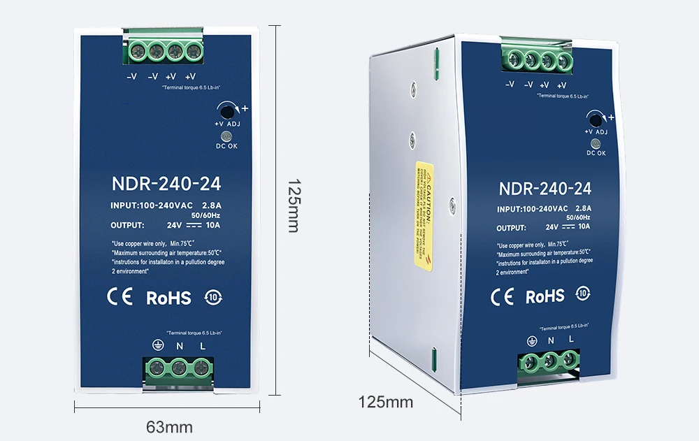
| NDR-240-24 | 240W; 24V DC, 10A; input label 2.8A; W × H × D: 63 × 125 × 125mm |

Input, output and protection
| AC input | 100–240V AC, 50/60Hz |
|---|---|
| Output adjustment | ADJ control; ±10% reference in the source description |
| DC indication | Front DC OK indicator |
| Protection functions | Overload, overvoltage, overcurrent and short circuit, as described in the source |
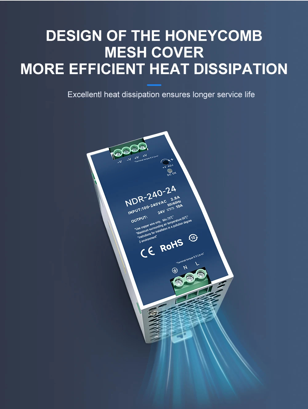
| Cooling | Free-air convection through the metal enclosure and ventilation openings |
| Installation | DIN-rail mounting; rear clip and fixings shown in the gallery |
| Burn-in statement | The supplier states a 100% full-load burn-in test; no individual test record is supplied |
| Markings | The photographs carry CE and RoHS markings; no independent certificate is supplied with this material |

AC and DC terminal connections
Connect the AC supply to L and N and the protective-earth conductor to the ground terminal. Connect the DC load to +V and −V. Follow the terminal markings on the selected unit: the illustrated NDR-120-24 has two −V and two +V output terminals. The ADJ control changes the DC output setting; the DC OK indicator shows the output status.
The NDR-120-24 photograph marks terminal torque as 9 lb-in; the NDR-75-12 and NDR-240-24 references mark 6.5 lb-in. Use the marking on the actual model.

NDR-75-12 outline
12V DC, 6.25A; 75W model class. The original dimension drawing gives 31mm width, 125mm height and 112mm depth. Dimensions are photographic/manual-measurement references.

NDR-120-24 outline
24V DC, 5A; 120W model class. The original drawing gives 40mm width, 125mm height and 124mm depth.

NDR-240-24 outline
24V DC, 10A; 240W model class. The original drawing gives 63mm width, 125mm height and 125mm depth.
Ventilation and installation conditions
Keep the ventilation openings clear so that free-air convection can dissipate heat. The photographed labels specify copper conductors rated at least 75°C, a maximum surrounding air temperature of 50°C and installation in a pollution-degree-2 environment.
The shared source description separately gives an operating-temperature range of −20°C to +70°C, storage at −40°C to +85°C and ambient humidity of 0–95% without condensation. These shared values do not establish full-load operation at 70°C; the model label’s 50°C surrounding-air limit remains visible in the photographs. The source advises against bathroom use.
Construction and typical applications
The original construction illustration highlights capacitors and copper windings. The illustrated application fields include automation, instruments, electrical control, lighting, power systems, railway and communications equipment. These are application examples, rather than evidence of medical, aviation or rail approvals.

Available versions
The selectable versions on this page are limited to the three exact model/output combinations in the table. Other outputs and power sizes mentioned in the wider source series are not included as selectable configurations on this page.