


A faulty contactor can bring an entire production line to a halt. Before replacing what might be a perfectly good component, technicians should perform systematic diagnostic tests. This step-by-step guide shows you how to test any industrial contactor using a standard digital multimeter.
Whether you’re troubleshooting a motor starter, HVAC system, or lighting control, these tests will help you determine if the contactor is the culprit—or if the problem lies elsewhere.
Understanding Contactor Basics
What You’ll Be Testing
A contactor consists of three main components:
1. Coil (Electromagnet) – Creates magnetic field to close contacts 2. Main Contacts – Carry load current to the motor/equipment 3. Auxiliary Contacts – Used for control circuits and interlocking
Common Failure Modes
| Symptom | Likely Cause | Test Required |
|---|---|---|
| Contactor won’t energize | Open coil | Coil resistance |
| Contactor chatters | Low voltage, weak coil | Coil voltage |
| Welded contacts | Overcurrent, excess cycles | Contact continuity |
| Intermittent operation | Poor connections | Terminal tightness |
Required Tools
Essential Equipment
- Digital Multimeter (with resistance and continuity modes)
- Insulated Screwdrivers
- Safety Gloves (rated for electrical work)
- Lockout/Tagout Equipment
Multimeter Settings
- Resistance (Ω): For coil testing
- Continuity: For contact testing (audible beep preferred)
- AC/DC Voltage: For coil voltage verification
Step 1: Safety First – Lockout/Tagout
Critical Safety Steps
⚠️ Never work on energized equipment
1. Disconnect power at the main breaker 2. Verify zero energy with your multimeter 3. Apply lockout/tagout devices 4. Test on known live source before and after testing
Remember: Capacitors in VFDs and drive circuits can store lethal voltage even after power is removed.
Step 2: Visual Inspection
What to Look For
Before reaching for your multimeter, perform a thorough visual check:
Contact Condition:
- ✓ Silver-gray appearance (normal)
- ✗ Blackened, pitted, or melted contacts (replace)
- ✗ Excessive carbon buildup (clean or replace)
Coil Housing:
- ✓ No burn marks or discoloration
- ✗ Burnt smell indicates coil failure
- ✗ Cracked housing (moisture ingress)
Mechanical Components:
- Check for broken springs
- Verify contactor moves freely (manually operate)
- Look for foreign objects or debris
Step 3: Test the Coil Resistance
Why This Test Matters
The coil is the most common failure point. A healthy coil has predictable resistance based on its voltage and power rating.
Testing Procedure
Step 3a: Locate Coil Terminals
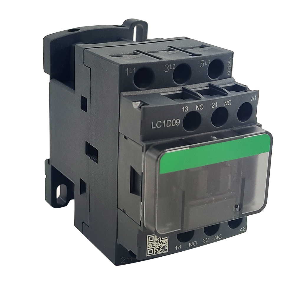
- Coil terminals are typically marked A1 and A2
- May also be labeled with coil voltage (e.g., “24V DC”, “220V AC”)
Step 3b: Set Your Multimeter
- Select resistance (Ω) mode
- Choose appropriate range (usually 200Ω or 2kΩ)
Step 3c: Measure Resistance 1. Disconnect wires from A1 and A2 2. Place probes on A1 and A2 terminals 3. Record the reading
Interpreting Results
Expected Resistance Values (Typical Ranges):
| Coil Voltage | Expected Resistance | Acceptable Range |
|---|---|---|
| 24V AC | 15-30Ω | ±20% |
| 120V AC | 300-500Ω | ±20% |
| 220-240V AC | 1000-3000Ω | ±20% |
| 24V DC | 100-500Ω | ±20% |
| 48V DC | 400-1500Ω | ±20% |
Reading Analysis:
| Result | Interpretation | Action |
|---|---|---|
| 0Ω (short) | Coil winding shorted | Replace contactor |
| Infinite (∞) | Open coil winding | Replace contactor |
| Within range | Coil is healthy | Proceed to contact tests |
| Outside ±20% | Coil degraded | Consider replacement |
Example: A 220V AC coil measures 2.5kΩ. Expected range: 1-3kΩ. Result: PASS
Step 4: Test Main Contact Continuity
Understanding the Test
Main contacts should have near-zero resistance when closed and infinite resistance when open.
Testing Procedure
Step 4a: Identify Main Contact Terminals
- Line side: L1, L2, L3 (input)
- Load side: T1, T2, T3 (output to motor)
Step 4b: Test with Contactor De-energized (Open) 1. Set multimeter to continuity or resistance (Ω) 2. Test between L1 and T1, L2 and T2, L3 and T3 3. Expected: No continuity (infinite resistance) 4. Any reading other than infinity indicates welded contacts
Step 4c: Manually Activate and Test (Closed) 1. Press contactor mechanism manually (or apply rated voltage to coil) 2. Test between L1 and T1, L2 and T2, L3 and T3 3. Expected: Continuity (<1Ω) on all three poles 4. High resistance indicates dirty or damaged contacts
Interpreting Results
| Condition | De-energized | Energized | Diagnosis |
|---|---|---|---|
| Normal | ∞Ω (open) | <1Ω (closed) | ✓ Healthy |
| Welded contacts | <1Ω | <1Ω | ✗ Replace immediately |
| Burnt contacts | ∞Ω | >5Ω | ✗ Clean or replace |
| Single pole failed | ∞Ω | L1-T1 OK, L2-T2 ∞Ω | ✗ Replace contactor |
Step 5: Test Auxiliary Contacts
Test Procedure
Auxiliary contacts follow the same testing logic:
Normally Open (NO) Contacts:
- De-energized: ∞Ω
- Energized: <1Ω
Normally Closed (NC) Contacts:
- De-energized: <1Ω
- Energized: ∞Ω
Common Terminal Designations:
- 13-14: NO auxiliary
- 21-22: NC auxiliary
- 53-54: Additional NO
Step 6: Verify Coil Voltage (If Accessible)
Why This Matters
A contactor with a good coil may still fail to operate if supply voltage is incorrect.
Testing Procedure
Step 6a: With Power On (Qualified Personnel Only) 1. Set multimeter to AC or DC voltage (match coil rating) 2. Measure voltage at coil terminals A1-A2 3. Compare to contactor coil rating
Acceptable Voltage Range:
- Minimum: 85% of rated voltage
- Maximum: 110% of rated voltage
Example: For 220V AC coil:
- Minimum: 220V × 0.85 = 187V AC
- Maximum: 220V × 1.10 = 242V AC
| Voltage Reading | Status |
|---|---|
| 198V – 242V | ✓ Normal operation |
| <187V | ✗ Undervoltage – check supply |
| >242V | ✗ Overvoltage – risk of coil damage |
Step 7: Advanced Tests (Optional)
Insulation Resistance Test
Purpose: Detect coil-to-ground or terminal-to-terminal leakage
Procedure: 1. Use megohmmeter (500V DC) 2. Test coil terminals to contactor frame 3. Test line terminals to load terminals (open position)
Acceptable: >10 MΩ Unacceptable: <1 MΩ (moisture/dirt contamination)
Inrush Current Measurement
Purpose: Verify coil is drawing expected inrush current
Typical Inrush: 5-15× holding current for AC coils
High Inrush (>20×): Indicates shorted turns in coil
Troubleshooting Decision Tree
` Contactor Won’t Energize ↓ Check Control Voltage at A1-A2 ↓ ┌──────────┴──────────┐ No Voltage Correct Voltage ↓ ↓ Check wiring/ Measure Coil Resistance control circuit ↓ ┌────┴────┐ Infinite 0Ω Normal ↓ ↓ ↓ Open coil Shorted Check (Replace) (Replace) mechanically `
Common Misdiagnoses to Avoid
❌ Misdiagnosis 1: “Contactor is bad”
Actually: Control fuse blown, emergency stop pressed, or interlock open
❌ Misdiagnosis 2: “Contacts are welded”
Actually: Mechanical binding preventing full opening
❌ Misdiagnosis 3: “Coil needs replacement”
Actually: Low control voltage from undersized transformer
When to Replace vs. Repair
Replace the Contactor When:
- Coil resistance is open or shorted
- Main contacts are welded or severely pitted
- Housing is cracked or damaged
- Multiple failures in short time period
- Unit is >10 years old with heavy cycling
Clean and Reuse When:
- Minor contact discoloration (use contact cleaner)
- Loose terminal screws (tighten to spec)
- Dust/debris contamination (clean with dry cloth)
Related products on our website
If you want to compare similar options or move from article reading to product review, start with these links:
Conclusion
Systematic multimeter testing can diagnose 90% of contactor problems in under 10 minutes. By following this step-by-step procedure, you’ll avoid unnecessary replacements and minimize equipment downtime.
Remember: Always verify power is off before testing, and never exceed manufacturer ratings during troubleshooting.
Recommended Testing Equipment
For professional electrical maintenance, we recommend:
- Fluke 117 Electrician’s Multimeter – Industry standard
- Megger MIT1025 – For insulation testing
- NewTrend LC1D Series Contactors – Reliable replacement units
[Browse Our Contactor Catalog →] | [Contact Technical Support →]