


Industrial automation has evolved far beyond simple relay logic. Modern manufacturing and process control systems demand seamless integration between traditional power components—contactors and relays—and sophisticated Programmable Logic Controllers (PLCs). This integration enables centralized monitoring, predictive maintenance, and the Industrial Internet of Things (IIoT) capabilities that define Industry 4.0.
This technical guide explores practical methods for integrating relays and contactors with PLC systems, covering wiring architectures, communication protocols, and implementation best practices.
Why Integrate Contactors with PLCs?
Traditional vs. Modern Control
Traditional Hardwired Control:
- Physical pushbuttons and selector switches
- Interconnected relays for logic functions
- Limited diagnostics
- Difficult to modify
PLC-Based Control:
- Software-based logic programming
- Centralized monitoring and control
- Rich diagnostic data
- Flexible, easily modified
Benefits of Integration
1. Centralized Monitoring
- Real-time status of all contactors and relays
- Historical data for trend analysis
- Alarm management and notification
2. Predictive Maintenance
- Cycle counting for contact wear prediction
- Coil current monitoring for degradation detection
- Temperature monitoring for thermal issues
3. Energy Management
- Motor run-time tracking
- Load profiling and optimization
- Automated demand response
4. Safety Enhancement
- Fail-safe programming
- Safety PLC integration (SIL rated)
- Emergency stop coordination
Integration Architectures
Architecture 1: Discrete I/O (Basic)
Components:
- Standard contactor with auxiliary contacts
- PLC digital input modules
- PLC digital output modules
- Interposing relays (if needed)
Wiring Scheme: ` PLC Output (24V DC) → Relay Coil → Contactor Coil (A1-A2) Contactor Aux Contact (NO) → PLC Input → Common `
Typical I/O Assignment:
- DO-01: Start Motor 1
- DI-01: Motor 1 Running Status
- DI-02: Motor 1 Fault/Tripped
Advantages:
- Simple, reliable
- Low cost
- Fast response
Limitations:
- Limited diagnostic information
- Extensive wiring
- No parameter data
Architecture 2: Smart Contactors with Communication
Components:
- Smart contactors with built-in electronics
- Communication module (Modbus, Profinet, EtherNet/IP)
- PLC with matching communication capability
Data Exchange:
- Contact status (open/closed)
- Coil voltage/current
- Number of operations (cycle count)
- Temperature
- Fault diagnostics
Communication Protocols:
| Protocol | Medium | Speed | Best For |
|---|---|---|---|
| Modbus RTU | RS-485 | 115.2 kbps | Simple, cost-effective |
| Modbus TCP | Ethernet | 100 Mbps | Modern installations |
| Profinet | Ethernet | 100 Mbps | Siemens environments |
| EtherNet/IP | Ethernet | 100 Mbps | Rockwell/Allen-Bradley |
| CANopen | CAN bus | 1 Mbps | Automotive, mobile |
Advantages:
- Rich diagnostic data
- Reduced wiring
- Remote monitoring capability
Limitations:
- Higher component cost
- Network complexity
- Single point of failure (network)
Architecture 3: Hybrid System (Recommended)
Components:
- Standard contactors for power switching
- Current transformers for load monitoring
- Temperature sensors for thermal monitoring
- VFDs or soft starters with communication
- Central PLC with HMI
Implementation:
- Hardwired safety interlocks (critical for safety)
- Communication for monitoring and control
- Separate safety PLC if SIL rating required
Advantages:
- Cost-effective
- High reliability
- Comprehensive monitoring
- Safety compliance
Wiring Best Practices
Input Wiring (Status Monitoring)
Standard Approach: ` Contactor Aux Contact (13-14 NO) ↓ PLC Input Module (24V DC, Sinking) ↓ PLC Common (0V) `
With Interposing Relay (High Voltage Isolation): ` Contactor Aux Contact (220V AC) ↓ Relay Coil ↓ Relay Contact (24V DC) ↓ PLC Input `
Wiring Considerations:
- Use separate commons for AC and DC circuits
- Implement proper surge protection
- Shield cables in high-noise environments
- Maintain voltage compatibility
Output Wiring (Control)
Direct Connection (Low Power Coils): ` PLC Output (24V DC, 0.5A max) ↓ Contactor Coil (A1-A2, 24V DC) `
With Interposing Relay (High Power or AC Coils): ` PLC Output (24V DC) ↓ Relay Coil (24V DC, low power) ↓ Relay Contact ( Rated for contactor coil) ↓ Contactor Coil (220V AC or high-power DC) `
Important: Always check PLC output rating vs. contactor coil inrush current
PLC Programming for Contactor Control
Basic Motor Control Logic
Ladder Logic Example (Start/Stop): ` | | | Start Stop Run | |—-] [—-+–]/[—-+—-( )——————————-| | | | | | +———+ | | | | Run Motor_Out | |—-] [————-( )————————————| | | `
Structured Text Equivalent: `pascal IF Start_Button AND NOT Stop_Button THEN Motor_Running := TRUE; END_IF;
IF Stop_Button THEN Motor_Running := FALSE; END_IF;
Motor_Contactor := Motor_Running; `
Advanced Control Features
1. Cycle Counting for Maintenance: `pascal IF Contactor_Closed AND NOT Contactor_Closed_Previous THEN Cycle_Counter := Cycle_Counter + 1; END_IF; Contactor_Closed_Previous := Contactor_Closed;
IF Cycle_Counter >= Maintenance_Threshold THEN Maintenance_Alarm := TRUE; END_IF; `
2. Current Monitoring: `pascal Actual_Current := AI_Current_Sensor;
IF Actual_Current > Overload_Setpoint THEN Overload_Timer := Overload_Timer + 1; ELSE Overload_Timer := 0; END_IF;
IF Overload_Timer >= Overload_Delay THEN Trip_Motor(); Overload_Alarm := TRUE; END_IF; `
3. Sequencing Multiple Motors: `pascal // Sequential start with 5-second delay CASE Motor_Sequence OF 0: // Idle IF Start_Sequence THEN Motor_Sequence := 1; END_IF;
1: // Start Motor 1 Motor1_Run := TRUE; IF Motor1_Confirmed THEN Sequence_Timer := 0; Motor_Sequence := 2; END_IF;
2: // Wait 5 seconds Sequence_Timer := Sequence_Timer + 1; IF Sequence_Timer >= 5000 THEN // 5 seconds Motor_Sequence := 3; END_IF;
3: // Start Motor 2 Motor2_Run := TRUE; IF Motor2_Confirmed THEN Motor_Sequence := 4; // Running END_IF;
4: // Running IF Stop_Sequence THEN Motor_Sequence := 5; END_IF;
5: // Stop sequence Motor2_Run := FALSE; IF NOT Motor2_Confirmed THEN Motor1_Run := FALSE; Motor_Sequence := 0; END_IF; END_CASE; `
Communication Protocol Implementation
Modbus RTU Example
Network Configuration:
- Master: PLC with RS-485 port
- Slaves: Smart contactors (addresses 1-10)
- Baud rate: 19,200
- Data format: 8-N-1
Typical Register Map:
| Register | Description | Data Type |
|---|---|---|
| 40001 | Contactor Status | Boolean |
| 40002 | Coil Voltage | UINT16 (×0.1V) |
| 40003 | Cycle Count Low | UINT16 |
| 40004 | Cycle Count High | UINT16 |
| 40005 | Temperature | INT16 (°C) |
| 40006 | Fault Code | UINT16 |
Read Command (Function 03): ` Request: [01] [03] [00 00] [00 06] [CRC] Response: [01] [03] [0C] [data…] [CRC] `
Safety Considerations
Functional Safety (SIL)
When contactor control affects personnel safety:
Required Elements:
- Safety PLC (SIL 2 or SIL 3 rated)
- Safety contactors with positively-guided contacts
- Redundant monitoring (dual-channel)
- Proof testing protocols
Safety PLC Programming:
- Use certified function blocks
- Implement safe torque-off (STO) where applicable
- Document all safety functions
- Regular verification testing
Emergency Stop Integration
Hardwired E-Stop Circuit (Always Required): ` E-Stop Contact (NC) → Safety Relay → Contactor Coil ↓ PLC Input (monitoring only) `
Never rely solely on PLC for emergency stop!
IIoT and Cloud Integration
Data Collection Architecture
Edge Layer:
- PLC with data logging
- Local HMI for operators
- Historical data storage
Gateway Layer:
- OPC-UA server
- MQTT broker
- Protocol converters
Cloud Layer:
- AWS IoT, Azure IoT, or private cloud
- Analytics and visualization
- Predictive maintenance algorithms
Key Performance Indicators (KPIs)
Equipment-Level KPIs:
- Motor runtime hours
- Start/stop cycle count
- Average current draw
- Number of overload trips
System-Level KPIs:
- Overall Equipment Effectiveness (OEE)
- Energy consumption per unit
- Mean Time Between Failures (MTBF)
- Maintenance cost per asset
Troubleshooting Guide
Common Integration Issues
Problem: Contactor chatters
- Cause: PLC output voltage/current insufficient
- Solution: Use interposing relay or higher-rated output
Problem: False status indications
- Cause: Electrical noise on input wiring
- Solution: Add filtering, use shielded cable, check grounding
Problem: Communication timeouts
- Cause: Network loading, cable issues
- Solution: Check termination, reduce polling rate, verify addresses
Problem: Slow response time
- Cause: PLC scan time too long
- Solution: Optimize program, use immediate I/O updates
Cost-Benefit Analysis
Basic Integration (Discrete I/O)
Additional Costs:
- PLC I/O modules: $50-100 per point
- Wiring and installation: $20-50 per point
- Programming: Initial setup
Benefits:
- Centralized control
- Basic monitoring
- Reduced maintenance time: 20-30%
ROI: Typically 1-2 years
Advanced Integration (Smart Components + Communication)
Additional Costs:
- Smart contactors: 2-3× standard cost
- Communication infrastructure: $500-2000
- Programming and integration: Higher complexity
Benefits:
- Predictive maintenance
- 40-60% reduction in unplanned downtime
- Energy optimization: 10-15% savings
ROI: Typically 2-3 years
Product Recommendations
Standard Integration (Discrete I/O)
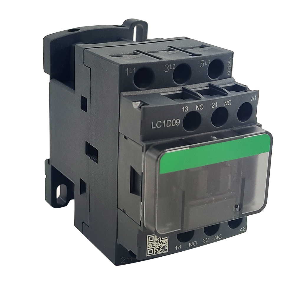
Contactors:
- NewTrend LC1D Series with auxiliary contacts
- Available with 1NO+1NC or 2NO+2NC auxiliaries
- Reliable for millions of operations
Interface Relays:
- Slimline 24V DC relays for PLC outputs
- 6A contact rating for contactor coil switching
- LED status indication
Smart Integration (Communication)
Smart Contactors:
- Electronic coil with diagnostic capabilities
- Modbus communication option
- Integrated current monitoring
Communication Gateways:
- Modbus RTU to TCP converters
- Multi-protocol support
- DIN rail mounting
Related products on our website
If you want to compare similar options or move from article reading to product review, start with these links:
Conclusion
Integrating relays and contactors with PLC control systems is fundamental to modern industrial automation. Whether implementing a basic discrete I/O system or a sophisticated IIoT-enabled architecture, proper planning ensures reliable operation and long-term value.
Key Success Factors:
- Match architecture to application requirements
- Never compromise safety for convenience
- Plan for future expansion
- Implement proper diagnostics from day one
Ready to modernize your motor control systems? Our application engineers provide complete integration support, from component selection to PLC programming assistance.
[Download PLC Integration Guide →] | [Request System Design Consultation →]